Faculty Guide
- Professor B Venkatesa Perumal
Mentors
- Kaushik Alwala
- Adithya Kannan
Members
- Rohan Rao
- Nakshatra Gopi
Wireless Battery Charger
Long wires and them getting entangled is something not everyone likes in the modern age. With things like wireless chargers becoming popular, this project deals with making a wireless battery charger from the ground up using concepts like Power Electronics. Since it’s wireless, the final hardware is divided into two separate parts—the Transmitter and Receiver, made on two different PCB(Printed Circuit Boards) boards. The two boards will be connected via mutual coupling of inductors, as explained later.
Part 1: The Transmitter
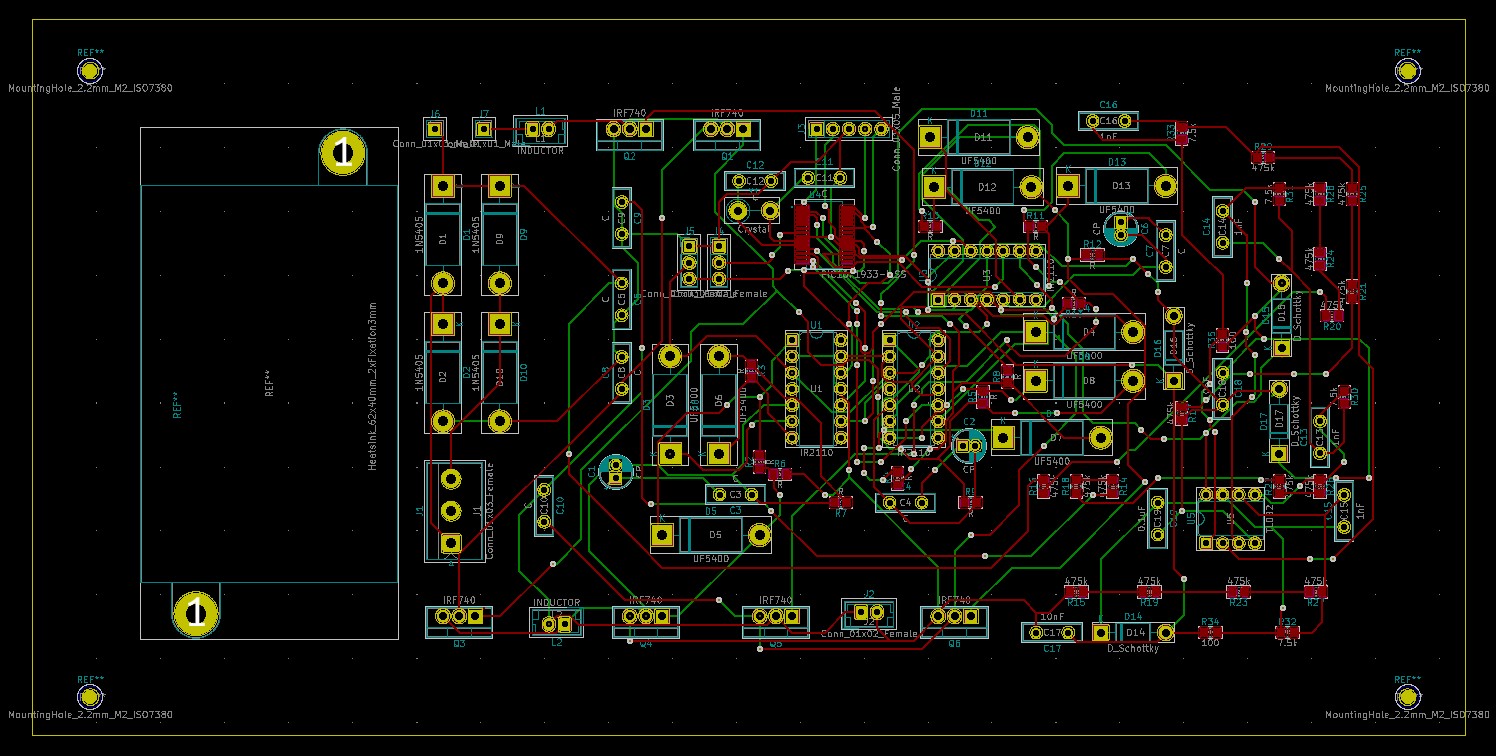
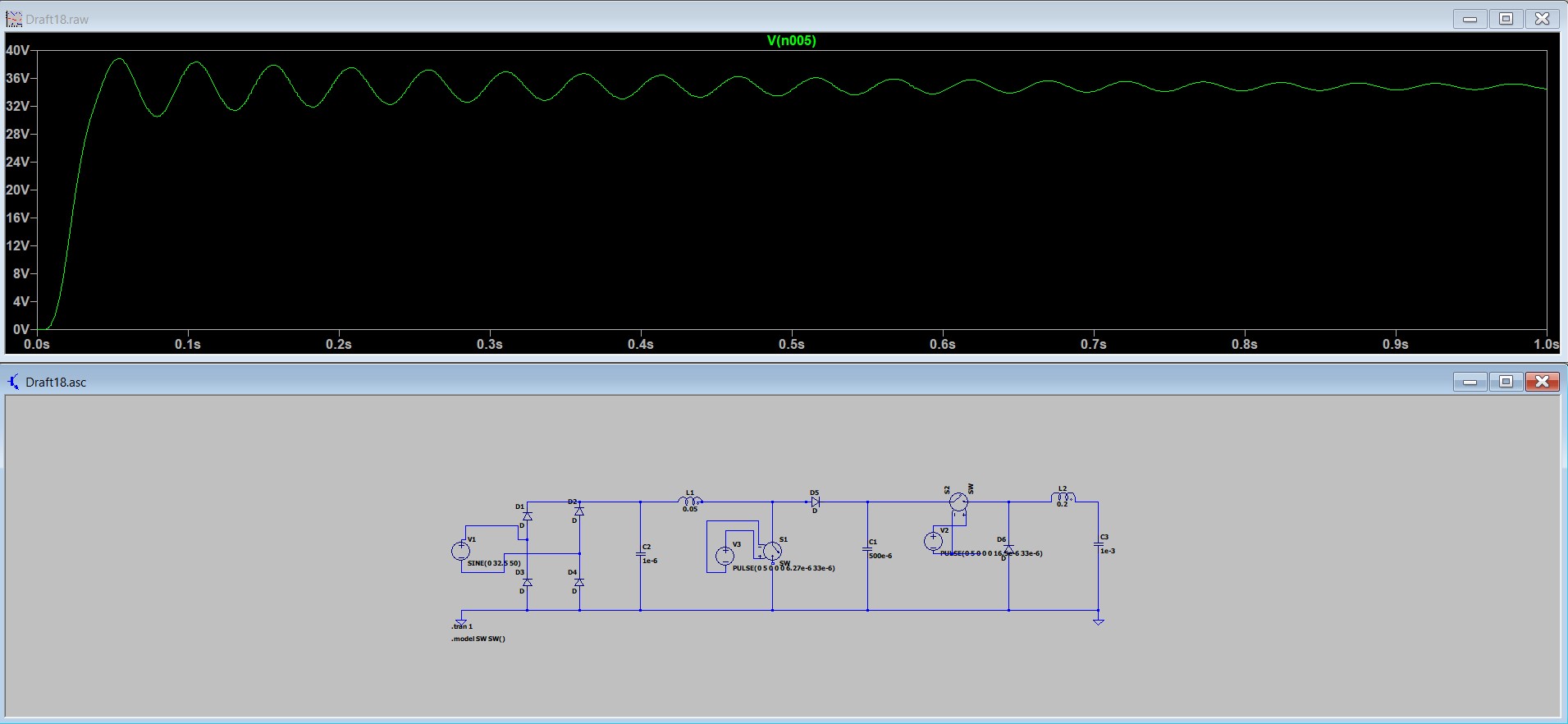
The transmitter takes input from the power grid, which is 230 V, 50 Hz AC voltage. And this is passed through a rectifier to get a DC output. With the help of boost and buck(cascaded together), the DC voltage is brought around 100 V. The circuit for the same was first designed, and the simulation was tested as shown in Fig 3. The optimal power for the WPT(Wireless power transfer) was checked, and the voltage was brought down to 100 V for controlling a moderate current. LTSpice software was used for the simulation and evaluating the implementation. Once the circuit was finalized, the KiCAD was used to get a PCB design ready. The design is as shown in Fig 2. All the PCB board components were chosen for optimum space, and the ratings were also cross-verified. The microcontroller(PIC16F1933) was added to control the MOSFETs(metal-oxide-semiconductor field-effect transistor), And an additional heatsink component has also been added for them to the PCB.
Part 2: Coupling
The wireless power transmission is achieved by passing a high-frequency sine wave through a coil(transmitter coil) which is mutually coupled with another coil(receiver coil). The high-frequency sine wave is obtained with an inverter’s help, inverting the before mentioned 100V DC voltage. Both the transmitter and receiver coils are connected to a capacitor whose function is to balance the coil system’s leakage reactance. So the inverter’s switching frequency is decided based on the L, C, and k values of the coil and the capacitor system.
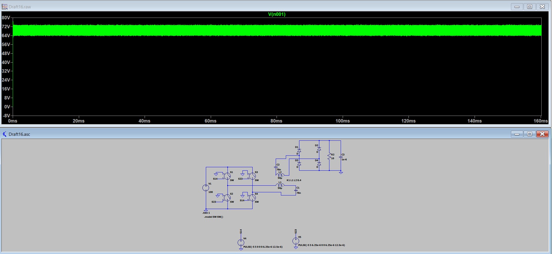
The image below shows the simulation for the coupling. The first image shows how the input is taken from the grid, which is 230V, 50Hz, and converted to DC. It consists of the AC-DC Converter and the DC-DC converters also to get a suitable voltage. The second image displays how the Wireless Power Transfer occurs, and the power is at the receiver end. The two separated coils shown in the image are the transmitter(L1) and receiver coil(L2) which are magnetically coupled.
Part 3: The Receiver
As shown in the previous image, at the receiver end, the voltage at the end of the coil and capacitor will be the same high-frequency sine wave sent at the transmitter end. This voltage is converted to DC voltage by a full bridge rectifier. The receiver will be charging a Li-ion battery. The DC voltage was passed through a buffer(ex: voltage following opamp) to avoid the distortions that may occur due to the charging algorithm’s implementation. The DC voltage available will now be used to charge a Lead acid battery. The charging algorithm was implemented with a PIC micro-controller.
Part 4: Implementation
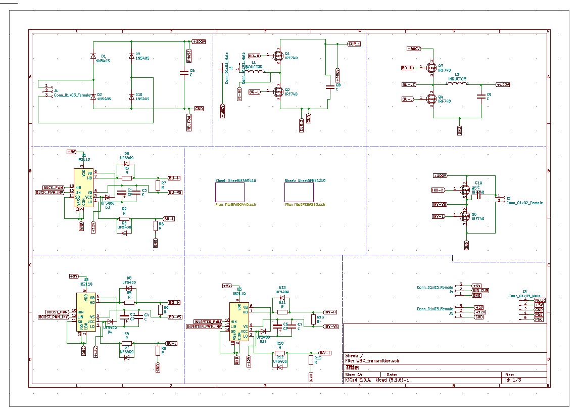
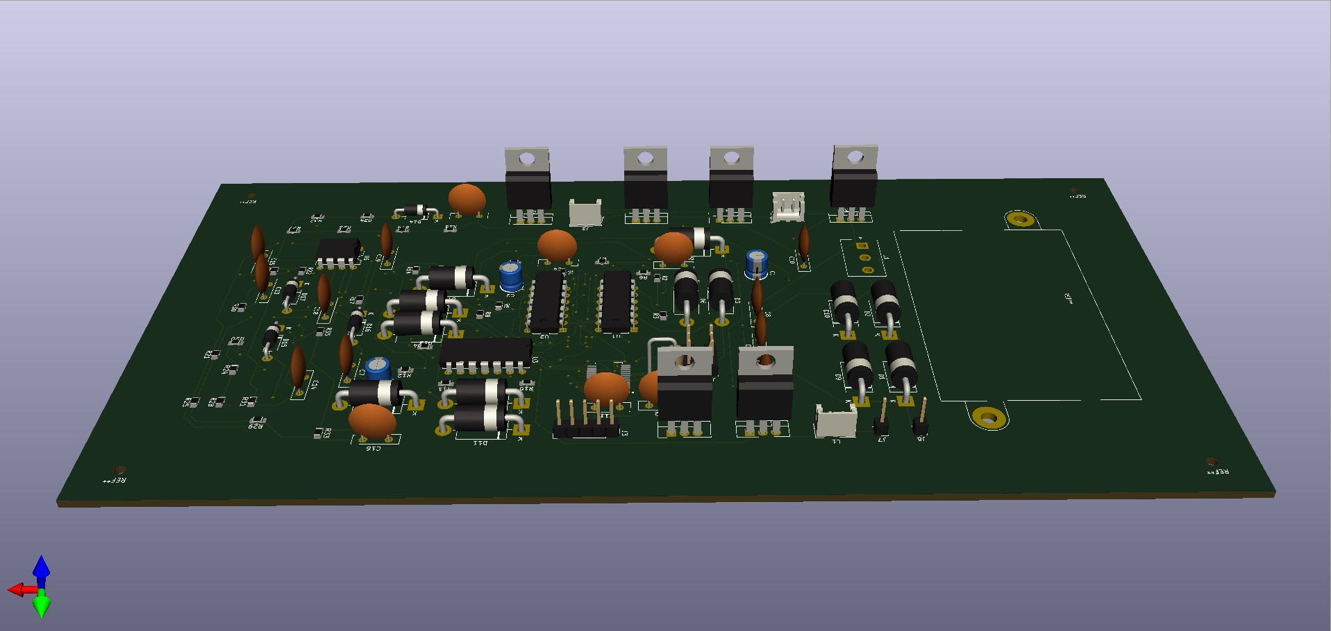
The schematic for the PCB design is as shown below. The components on the PCB appear as per this schematic. The routing done is manual. And the PCB is prepared. PCB image is as shown in the previous pictures.