Project Mentors
- Kartik Nayak
- Sharayu Brahmankar
Project Members
- Kaustubh
Abstract
Winglet is a type of wingtip device intended to improve the efficiency of fixed-wing aircraft by reducing drag. It works on the principle of recovering lost energy from tip vortex generation. Continuing growth of air traffic has made "wake vortex " one of the most challenging technical issues in modern civil aviation.
Winglets increase the aspect ratio of the wing while keeping the surface area relatively low which increases lift generation, and redirects the surrounding flow minimizing vortices. Since using winglets reduces the intensity of the wingtip vortices, less energy is lost from the air rotating outwards, which results in more thrust being available, while using the same amount of fuel.
Improved winglet efficiency enables more payload capacity, reduces fuel consumption while increases cruising range which all result in lower operating costs. By changing the configuration of the winglets, we can optimize the lift and reduce lift induced drag.
Objective
- To study the effect of winglets on the wing and to calculate the Cl/Cd ratio for different winglet designs and find the optimum design.
- Comparing the change in vortex formation between the different winglet designs.
Literature Survey
After doing the literature survey, we decided to choose the below-shown wing as our baseline wing. The factors that we came to know after the survey are as follows :
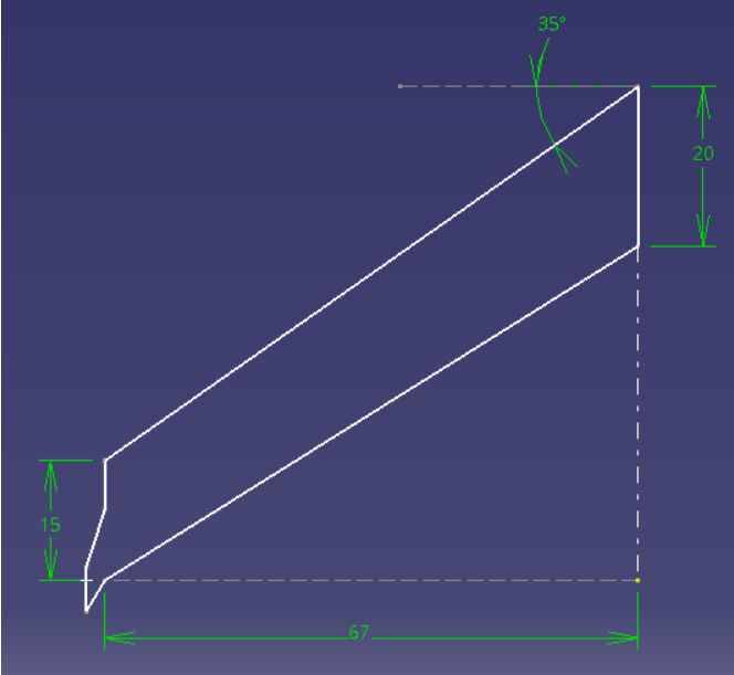
- Dimensions of wing are shown in fig
- Optimum Cant angle = 40deg
- Optimum height of winglet = 0.1 – 0.2 times semi span of wing, we have chose 0.1 [1]
- Optimum span of winglet = 15% of wingspan
- Aim: To optimize the sweep angle(30°, 45° and 60°) of winglets to maximize lift coefficient and minimize drag.
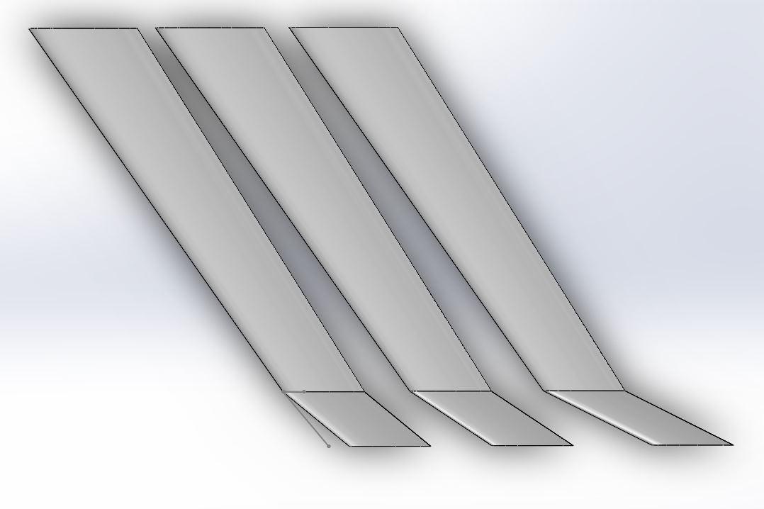
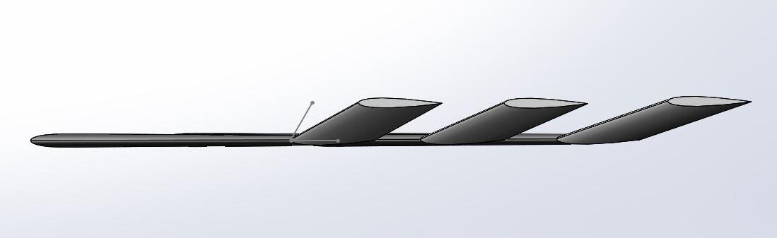
3D Models of the wing with different configurations of winglets
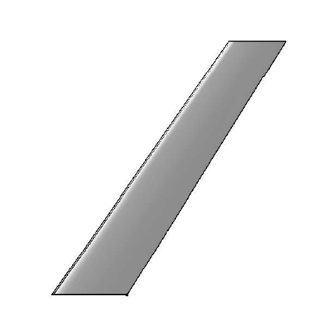
CAD models for the different configurations of winglets were designed on CATIA.
Aircraft design being a complex process has many phases in which Computer Aided Design (CAD) plays a significant role. Studies have been done on developing parameterized CAD models focusing to optimize the given model with less duration of time. CAD software tool CATIA was used in order to minimize the lead time and to avoid prolonged duration in the design process.
CAD model of the baseline wing.
CAD models of winglets with sweep angles of 30°, 45° and 60° respectively.
CFD Analysis using ANSYS
The CFD analysis of the 4 wing configurations was conducted using Ansys Fluent. The analysis can be split into four parts: Geometry, Meshing, Setup & Solution, and Results.
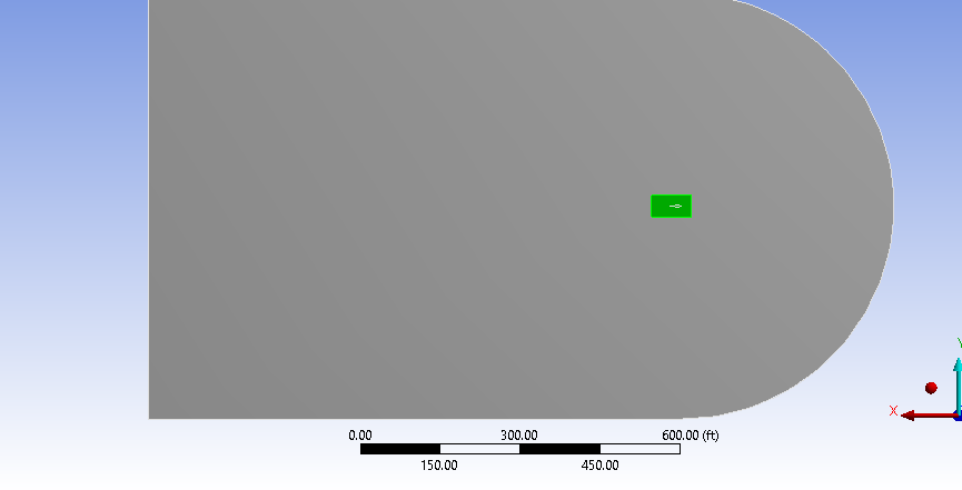
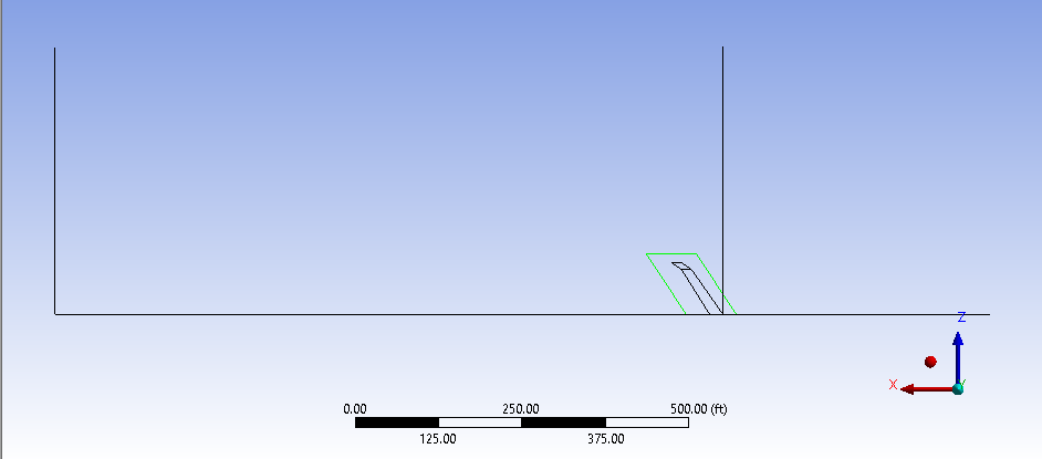
Geometry
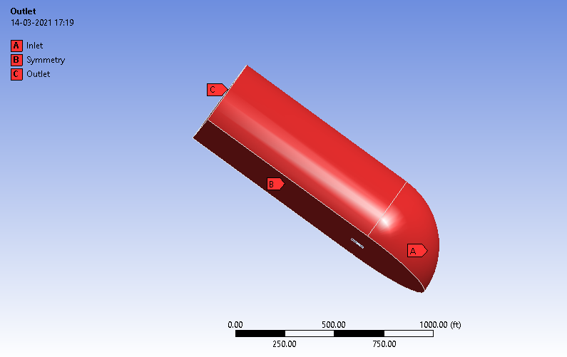
The models were imported into the Design modeler and the fluid domain was constructed within it. The fluid domain was a half – bullet consisting of a cuboidal and quarter sphere region. The wing was then subtracted from this region using the Boolean command. An extra domain for the body of influence was constructed around the wing.
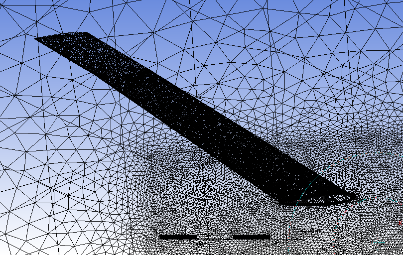
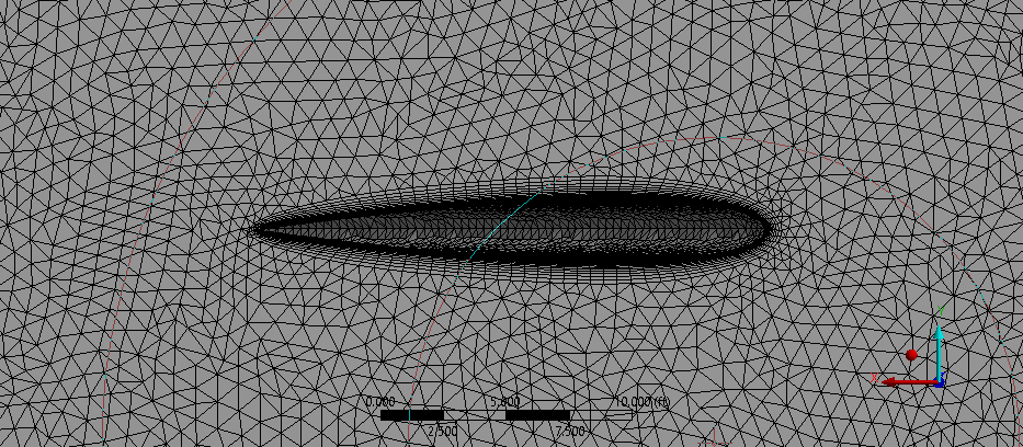
Meshing
Unstructured tetrahedral meshing was used. A body of influence and face sizing was used to obtain finer meshing in close proximity to the wing. An inflation based on the first layer thickness was provided. The first layer thickness was calculated based on the required Y+, which was chosen as 30 based on the literature study conducted. Finally, a grid independent study was conducted with a tolerance limit of 1%.
Setup & Solution
The following parameters were used for the setup:
- Reynold Number: 3 * 10^6
- Velocity: 0.6 Mach
- Model: Realizable K - Epsilon
- Boundary Conditions: Velocity Inlet, Symmetry, Pressure Outlet and the wing as a no slip wall.
- Method: Simple
The parameters were chosen based on the literature survey conducted.
Results
The results obtained from the analysis are as follows:
| Angle of Attack = 4° | ||||
|---|---|---|---|---|
| Type | C L | C D | C Di | C L/CD |
| Baseline | 2.858E-01 | 1.814E-02 | 1.037E-02 | 1.575E+01 |
| Sweep 30 | 3.073E-01 | 1.824E-02 | 9.163E-03 | 1.684E+01 |
| Sweep 45 | 3.068E-01 | 1.812E-02 | 9.174E-03 | 1.693E+01 |
| Sweep 60 | 3.053E-01 | 1.869E-02 | 9.179E-03 | 1.634E+01 |
| Angle of Attack = 6° | ||||
|---|---|---|---|---|
| Type | C L | C D | C di | C L/CD |
| Baseline | 4.137E-01 | 2.743E-02 | 2.329E-02 | 1.508E+01 |
| Sweep 30 | 4.308E-01 | 2.578E-02 | 2.059E-02 | 1.671E+01 |
| Sweep 45 | 4.307E-01 | 2.844E-02 | 2.060E-02 | 1.514E+01 |
| Sweep 60 | 4.241E-01 | 2.889E-02 | 2.062E-02 | 1.468E+01 |
| Angle of Attack = 8° | ||||
|---|---|---|---|---|
| Type | C L | C D | C Di | C L/CD |
| Baseline | 5.268E-01 | 5.078E-02 | 4.130E-02 | 1.037E+01 |
| Sweep 30 | 5.581E-01 | 5.070E-02 | 3.652E-02 | 1.101E+01 |
| Sweep 45 | 5.514E-01 | 5.232E-02 | 3.654E-02 | 1.054E+01 |
| Sweep 60 | 5.392E-01 | 5.392E-02 | 3.656E-02 | 1.000E+01 |
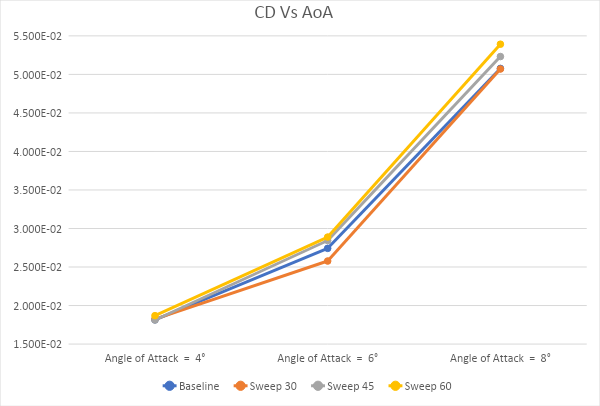
The graph for Coefficient of drag vs Angle of attack (CD vs AoA)
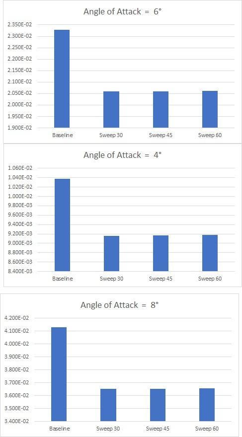
The comparisons of Induced drag for each angle of attack
Conclusion
From the tables and graphs, it can be clearly observed that the wing with the 30 degree sweep winglet was the best performing wing. It not only matched the baseline wing in C D values, but also gave a considerable increase in C L/CD while massively decreasing the induced drag at the same time.
References
[1] [9] Moore, T.. "The Effect of Winglet Twist and Toe Angle on the Drag of a High Aspect Ratio Wing." (2019).
[2] Panagi, Georgia. (2019). Investigation of winglet shapes on aerodynamic efficiency. 10.13140/RG.2.2.12243.81447.
[3] Bento Mattos, Antonini Macedo and Durval Silva Filho. "Considerations About Winglet Design,"AIAA 2003-3502. 21st AIAA Applied Aerodynamics Conference. June 2003.
[4] Design of Parametric Winglets and Wing tip devices – A Conceptual Design Approach Saravanan Rajendran
[5] Y. Nata, M. Ikhlas, I. Kurniawan and I. Sutiawan, "Optimizing the winglet model in getting the maximum power pressure using computational fluid dynamic (CFD)," 2017 International Conference on Computing, Engineering, and Design (ICCED), Kuala Lumpur, Malaysia, 2017, pp. 1-4.
[6] Smith, Marilyn & Komerath, Narayanan & Ames, Re & Wong, O. & Pearson, J.. (2001). Performance Analysis of a Wing With Multiple Winglets. 19th AIAA Applied Aerodynamics Conference. 11. 10.2514/6.2001-2407.
[7] Guerrero, Joel & Sanguineti, Marco & Wittkowski, Kevin. (2019). Variable cant angle winglets for improvement of aircraft flight performance A Preprint. 10.20944/preprints201907.0001.v1.
[8] Jacob Weierman and Jamey Jacob. "Winglet Design and Optimization for UAVs,"AIAA 2010-4224. 28th AIAA Applied Aerodynamics Conference. June 2010.
[9] Melin, Tomas. (2000). A Vortex Lattice MATLAB Implementation for Linear Aerodynamic Wing Applications.
[10] Gueraiche D, Popov S. Winglet Geometry Impact on DLR-F4 Aerodynamics and an Analysis of a Hyperbolic Winglet Concept. Aerospace. 2017; 4(4):60. Link