Project Mentors
- Akash Hemantrao Waitage
Project Members
- Monal Singh
Abstract
Today, technology is developing in the same direction in line with the rapidly increasing human needs. The work done to meet these needs makes life easier every day, and these studies are concentrated on robotics studies.
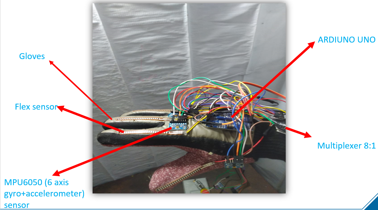
There are various types of robots present in the world, in which a humanoid robot is famous because it mimics a human being. AI or humans control humanoid robots through various sensors. This project builds a robotic arm with 13 DOF using a new wearable sensor model to control the humanoid robotic arm using gyro and flex sensors. Gyro sensors placed in a different position on a wearable material provide different angle values. Flex sensors are placed at each finger for sensing bending angle. We can define the configuration of a robotic arm with the mathematical model’s help.
Aim
The project aims to develop a mathematical model for successfully feeding configuration the same as the user’s hand. Cad modeling is done on Solidworks, testing and simulation are performed using MATLAB(Simulink).
The project is divided into three parts:
- Part Design and Manufacturing.
- Electronic and Circuitry.
- Simulation in Simulink.
Problem Statement
In today’s world, we need a controller to control robot motion. Even if we are advancing so much to give robot humans intelligence, robots cannot always make the right decision. Therefore, artificial intelligence is still vulnerable in this world, so we need a controller to control robots as humans command. So humans can operate in places where both human intelligence and robot strength are required.
Robotic Arm Mechanical Design
The robotic arm model used to test the results is the 13DOF planar robotic arm with link lengths in the ratio 3:2:1.
This study’s developed robot is a stationary articulated robotic arm with 13DOF, including base, shoulder, elbow, and gripper, including three revolute joints (wrist, fingers, elbow).
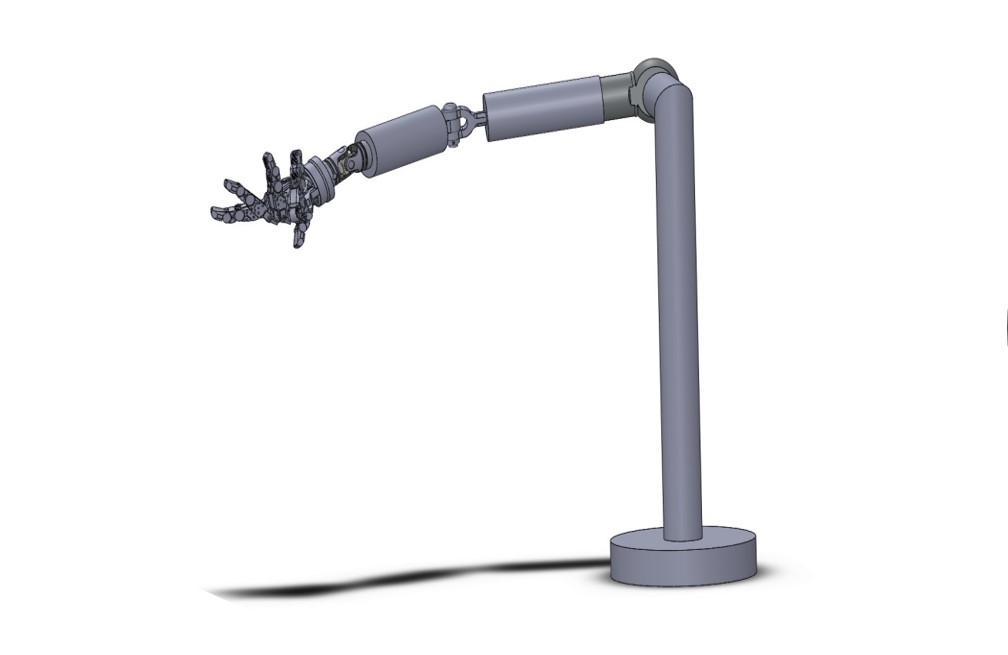
Wrist Joint
- Used universal Joint In-CAD Model
- Revolute Joints (In X & Y-Axis)
Elbow Joint
- Used knuckle Joint In-CAD Model.
- Revolute joint (Along Y-axis)
Finger Joint
- Revolute Joint
After all these careful measurements of all the robotic arm and rigorous part drawings, a CAD model was created using SolidWorks, according to the dimensions.
Robotic Arm Electronics
The basic operations of the controller are as follows:
- Sensors can be fixed to each joint whose orientation is required with the help of the controller.
- Provide orientation values of the sensors to the simulation software.
- Gives protection to the hardware.
Electric Components Used
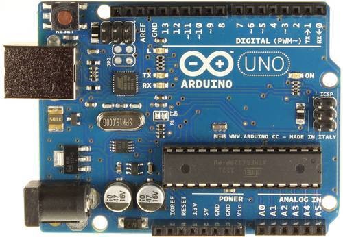
Arduino Uno Board
For Arduino, UNO atmega328 is used. It has a specification of 8-bit CPU, 16 MHZ clock speed, 2 KB SRAM 32 KB flash memory, 1 KB EEPROM [2].
The main features of the UNO Atmega328 are:
- Fourteen digital input-output pins (3,5,6,9,10, and 11 pins can generate PWM).
- Six analog input pins
- Voltage input from the 7 – 12 V
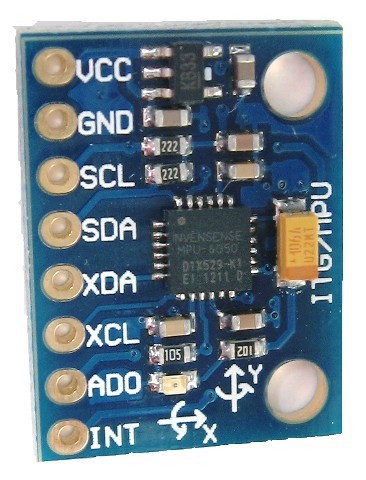
MPU-6050 six-axis (gyro + accelerometer)
We used an MPU6050, its six-axis called a 6 DoF (six Degrees of Freedom) device, as it provides six output values (three from Accelerometer and three from Gyro). The MPU-6050 can communicate using I2C Protocol.
The main features of the MPU6050 device are:
- Three-axis Accelerometer.
- Three-axis Gyroscope.
- Digital Output Temperature Sensor.
- Six 16-bit ADC (three for accelerometer and three for gyro).
- Integrated Digital Motion Processor (DMP).
Digital Motion Processor or the DMP is an embedded processor that can reduce the host processor’s computational load, like an Arduino, by acquiring and processing data from Accelerometer, Gyroscope, and an external Magnetometer.
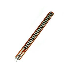
Flex Sensor
We used a 2.2inch Flex sensor that is FS-L-0055.
The main features of the Flex Sensor are:
- Operating voltage of flex sensor: 0-5V
- Can operate on low voltages
- Power rating: 0.5Watt (continuous), 1 watt (peak)
- Life: 1 million
- Operating temperature: -45ºc to +80ºc
- Flat resistance: 25K Ω
- Resistance tolerance: ±30%
- Bend resistance range: 45K to 125K ohms(depending on the bend)
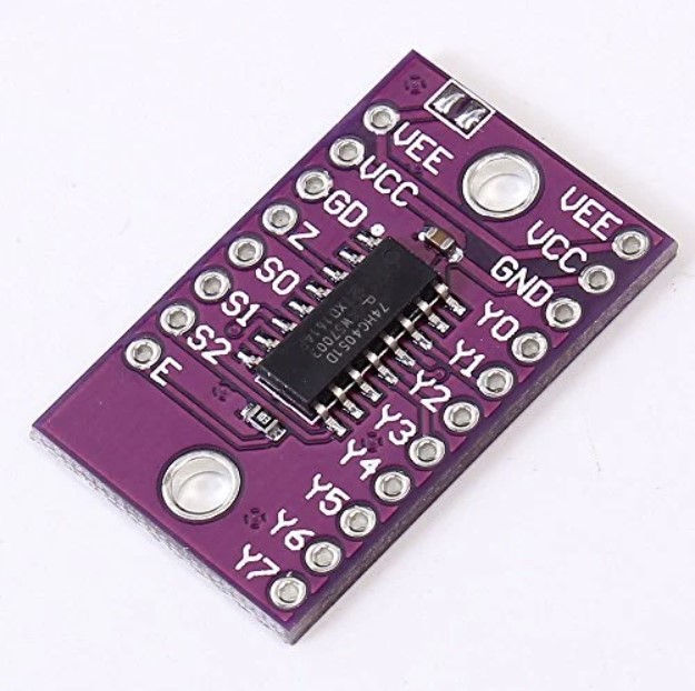
Multiplexer 8:1
An 8-to-1 multiplexer consists of eight data inputs D0 through D7, three input select lines S2 through S0, and a single output line Y. Depending on the preferred line combinations, multiplexer decodes the inputs.
Robotic Arm Simulation
- Data Collection Block:
This block is used to get values from the sensors.
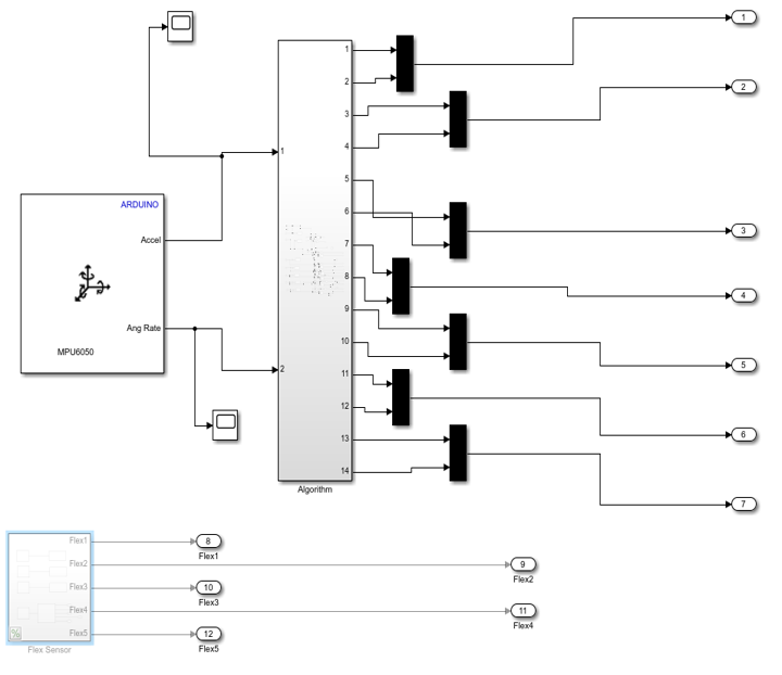
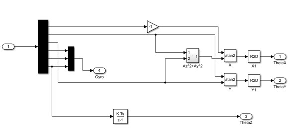
- Conversion block:
This block is used to convert sensors’ values to the angle of orientation.
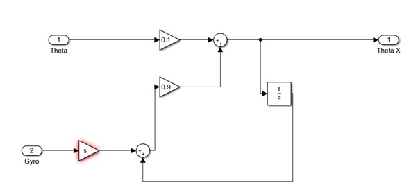
- Filter block:
We know that the accelerometer is suffered from noise. The gyro sensor is sustained from the deviation problem; we used a complementary filter for solving this issue.
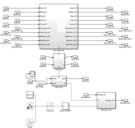
- Simscape Model:
After designing the cad model in Solidworks, we export the cad model into Simulink through Solidworks multibody option. We then add revolute joints where we want motion. Then, connect the input of revolute joints to the signals coming from the filter block to the respective joint.
Calculations
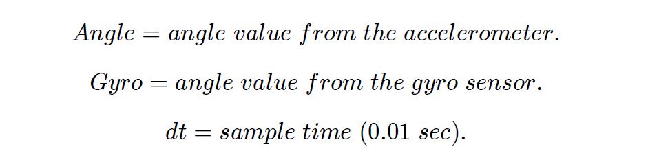
- Complementary filter equation:

where,
0<alpha<1,
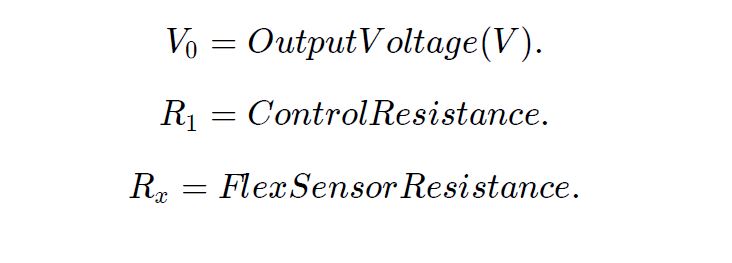
- Linear input Output relation for flex sensor:
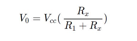
where,
Results
Working Model

Conclusion
The humanoid arm mimics the human being with the help of the controller. This document outlines the design and development of a controller and control system for operating the controller. We demonstrate the limb motion mimicry by converting sensor output into the rotation angle using MPU6050 and flex sensors.
References
[1] J. Hirth, k. Berns, k. Milanowski: “designing arms and hands for the humanoid robot roman,” advanced materials research · February 2012.
[2] Luk´aˇs palkoviˇc ∗ Jozef Rodina ∗∗ luboˇs Chovanec ˇ ∗∗∗ peter Dubinsky ∗∗∗∗: “integration of the inertial measuring unit platform into MATLAB Simulink,” conference paper · June 2012.
[3] A boyali, N Hashimoto and O Matsumoto: “paradigm shift in continuous signal pattern classification: mobile ride assistance system for two-wheeled mobility robots”, national institute of advanced industrial science and technology tsukuba, Ibaraki, Japan.
[4] Colin Kilby: “motion control of a robotic arm of a humanoid robot with a perspective difference,” carleton university ottawa, ontario,2015.
[5] Srđan savić1, mirko raković1, branislav borovac*1: “mechanical design and control algorithm for the arm of humanoid robot marko,” the 6th PSU-uns international conference on engineering and technology (ICET-2013), novi sad, serbia, may 15-17, 2013 the university of novi sad, faculty of technical sciences
[6] Hyunchul kim∗, levi makaio miller, nancy byl, gary m. Abrams, and jacob rosen: “redundancy resolution of the human arm and an upper limb exoskeleton”, IEEE transactions on biomedical engineering, vol. 59, no. 6, june 2012.
[7] 1 Chung-hsien kuo, 2 yu-wei lai, 3 kuo-wei chiu, 4 shih-tseng lee: “motion planning and control of interactive humanoid robotic arms”, IEEE international conference on advanced robotics and it is social impacts taipei, taiwan, aug. 23-25, 2008.
[8] A yudhana, j rahmawan, and c u p negara: “flex sensors and MPU6050 sensors responses on the smart glove for sign language translation”, October 2018IOP conference series materials science engineering 403(1):012032.