Project Guide
- Dr B V Perumal, Professor, Department of Mechanical Engineering, NITK Surathkal
Team Members
- Naman Agarwal
- Suraj Jagannath
- Kaushik Alwala
- Aditya C
Introduction
The project aims to develop a low cost and portable PV system using a modular approach. The project involved building an MPPT based battery charging circuit to charge a lead-acid battery using a solar panel, followed by an inverter circuit to power AC loads using the battery.
The MPPT battery charger is based on a buck topology, controlled by a PIC microcontroller on which the MPPT algorithm has been implemented. This system ensures maximum utilization of the solar panel by impedance matching while enabling safe charging of the battery to provide a long life.
The inverter is based on a push-pull topology with a 555 timer-based control circuit that generates the required pulses and an op-amp based driver circuit to drive the MOSFETS. This system uses the DC power supplied by the battery and generated AC pulses to be used by day to day appliances. Both these systems worked independently of one another.
Methodology
1. Inverter
- The inverter circuit is used to power AC loads using the DC supply from the lead-acid battery.
- It is based on a push-pull topology which enables us to use minimum components while keeping price low to achieve desired results.
- Square pulses of 50Hz are generated by the 555 timer. This pulse is inverted by the single NOT gate.
- Both these signals are then passed through an analog switch which enables us to implement the UVLO functionality
- The under-voltage lockout (UVLO) circuit is crucial to protect the battery and extend its life. This circuit compares the battery voltage to a fixed reference and turns off the MOSFET gate drives by controlling the analog switch, when the voltage of the battery drops below 9.6V, hence the battery is not pushed into a deep discharge state.
- The signals after passing through the analog switch are amplified using the OP-AMPs from 5V to 12V to ensure that the MOSFETs are driven to the fullest extent and hence the system functions with minimum losses.
- The square pulses of 12V on the primary of the transformer are then amplified to 240V AC on the secondary which powers loads.
2. Battery Charger
- The battery charging circuit is based on buck topology.
- This topology is employed as it efficiently steps down the 16V of the loaded solar panel to the 13V required to charge the battery while providing sufficient tolerance to change in solar panel output due to shading conditions.
- The buck converter is controlled using the IR2110 dual MOSFET driver IC to ensure efficient drive of the MOSFETs at a high frequency of 30kHz.
- The topology employed requires complementary square pulses of an appropriate duty cycle to be supplied to the IR2110 to control the gain of the buck converter.
3. Maximum Power Point Tracking (MPPT)
- The complementary control signals to the MOSFET driver are provided by the PIC16F684 microcontroller at a frequency of 30KHz.
- Operating at such a high frequency allows for a compact and efficient design.
- The duty cycle of the pulses is calculated using a Maximum Power Point Tracking (MPPT) algorithm.
- MPPT algorithm ensures that the impedance as seen by the solar panel is matched to the load impedance. Such impedance matching ensures that the maximum amount of power possible is derived from the solar panel.
- For such an algorithm to function, measurements of the voltage and current of both the battery and solar panel are required.
- These measurements are obtained using the four OP-AMPs on the board which are calibrated to provide scaled voltage readings which are sensed using the ADCs on the PIC MCU.
- The MPPT algorithm employed is Perturb and Observe (P&O) with a momentum term to speed up convergence. The flow diagram of the algorithm is:
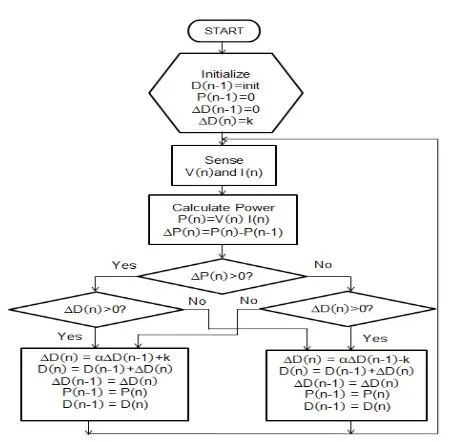
The circuit was tested using a solar panel simulator and the ability of the algorithm to accurately track the PV curve to the point of maximum power was observed.
Results
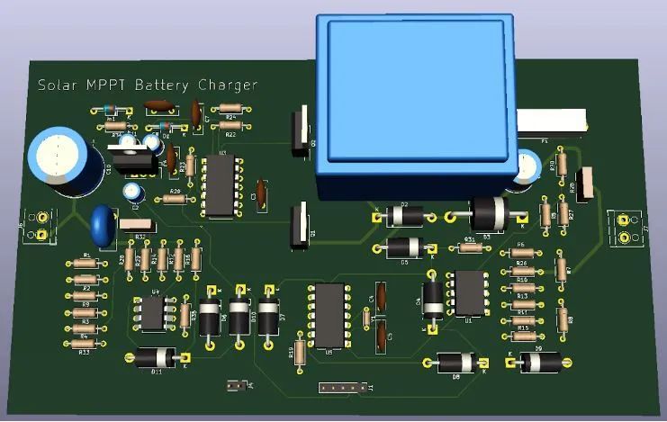
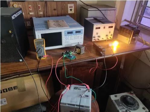
The image above shows our battery charger PCB cascaded with the inverter PCB at 50Hz. The buck converter provides a regulated DC supply as the output with the help of the MPPT algorithm on the PIC16F684.
The working of the DC-AC inverter connected to the battery, in full flow with a load is highlighted here.
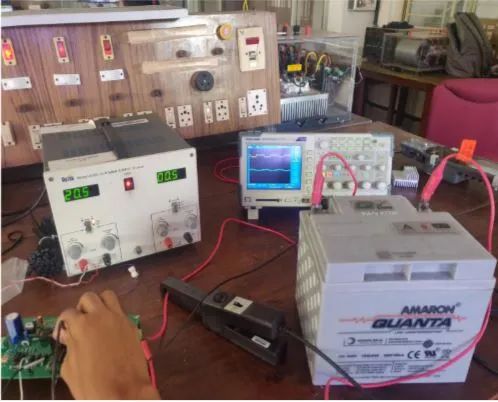
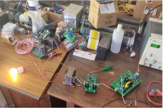
The MPPT based buck converter is shown here charging the battery from a DC box. The controlled testing here showed that our board can charge the 12V/40Ah battery in around 5hours from a 45W, 17.6V Vmp and 2.6A Imp panel. Charge current of up to 2Amps were obtained.
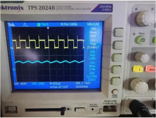
The oscilloscope shows the MOSFET gate pulse (yellow) for the buck regulator, which has been controlled by the MPPT code implemented on the PIC microcontroller. The blue waveform indicates the current fed into the battery during its charging cycle.
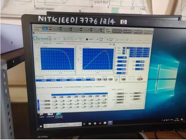
The MPPT algorithm tracks the PV curve to attain the maximum PowerPoint.
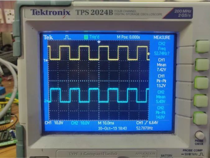
555 timer complementary pulses which eventually drives the MOSFET on the inverter circuit.
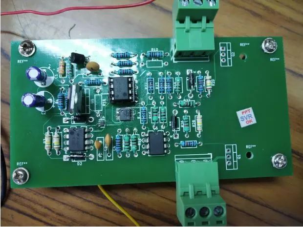
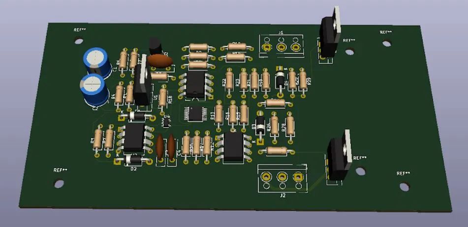
An image of the designed and populated inverter PCB.
Due to the Covid-19 pandemic and enforced lockdown, the testing of the solar inverter with multiple and different loads could not be done. The system can be used with multiple batteries and solar panel combinations considering their charging and discharging cycles along with maximum currents involved respectively.
References
- G. A. Raiker, “Dynamic Response of Maximum Power Point Tracking using Perturb and Observe Algorithm with Momentum Term,” 2017 IEEE 44th Photovoltaic Specialist Conference (PVSC), Washington, DC, 2017, pp. 3073-3076, doi: 10.1109/PVSC.2017.8366696.
- 14-Pin Flash-Based, 8-Bit CMOS Microcontrollers with nanoWatt Technology
Acknowledgement
It would be our utmost pleasure to express our sincere gratitude to our guide for this Project, Professor Dr B V Perumal for his vital support, constructive guidance and encouragement without which this project would not have come forth. His valuable guidance, support, advice, suggestions and supervision, all through this project, are responsible for attaining its present form and the corrections, modifications and improvements suggested by him enhanced the quality and accuracy of the project results. We would also like to thank Ms Roopa V for her constant support throughout the project. Finally, we thank IEEE NITK Student Branch for supporting the project.