Project Guide
- Dr Navin Karanth P., Associate Professor in the Department of Mechanical Engineering at NITK Surathkal
Mentors
- Siddh Narhari
- Kshamaa Acharya B
Members
- Akhil Guddati
- Krisha Shah
- Bhuvan AP
Acknowledgements
As executive members of IEEE NITK, we are extremely grateful for the opportunity to learn and work on this project under the prestigious name of the IEEE NITK Student Chapter and under the apprenticeship of Dr Navin Karanth P.
Aim
To design and develop a Soft Rotary Actuator which uses the peristaltic motion of elastomeric materials to achieve a stepper motor-like behaviour and is solely operated by compressed air.
Introduction
The goal of this project is to design and create a soft rotary actuator, which is a motor that can provide rotational motion but is powered only by compressed air (pneumatics). Although having no electrical components, this motor will function similarly to a stepper motor. This motor is safer and capable of functioning even in water because it lacks big sharp metallic bits and any onboard electronic components, unlike a typical motor which is made up of hefty metallic elements and electronic components.
The motor will be helpful in surveillance and rescue missions in extreme environments, even inside water bodies. Due to minimal metallic parts, it will also remain unaffected by the presence of magnetic fields. Therefore motors can also be used in devices which are highly sensitive to electric fields.
Methodology
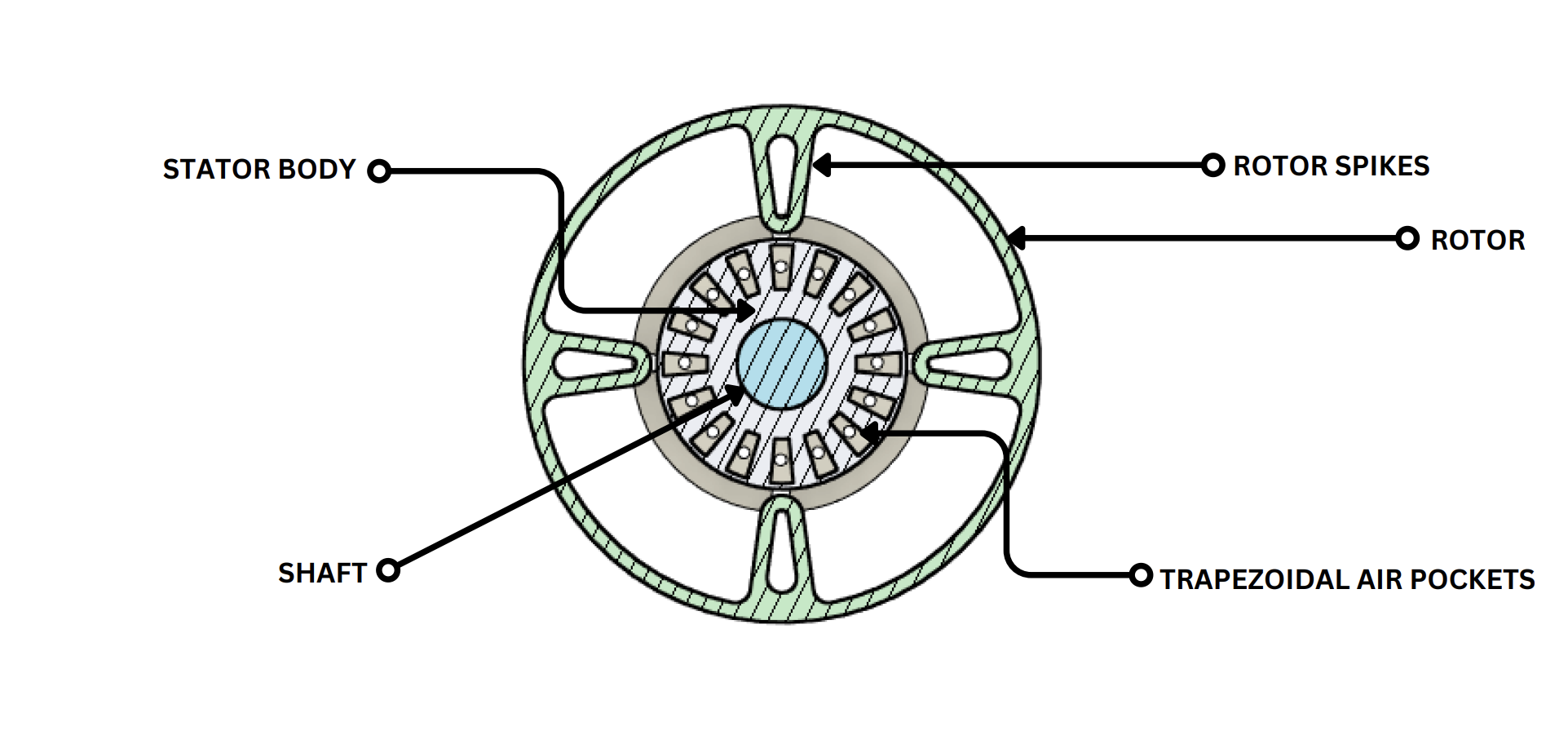
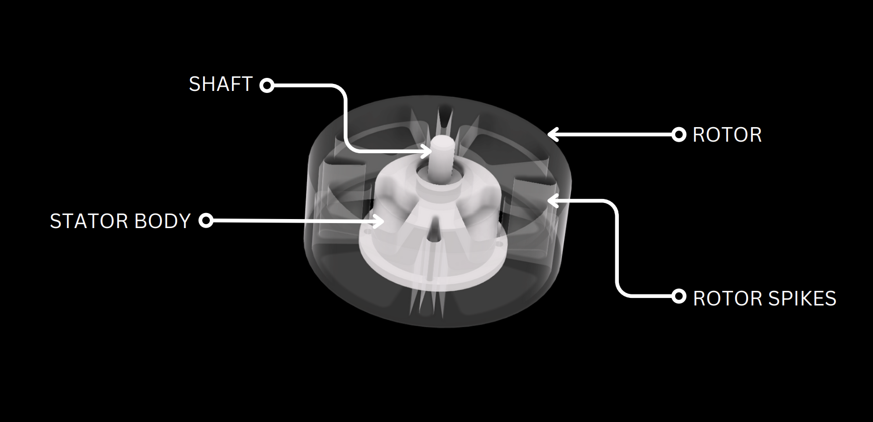
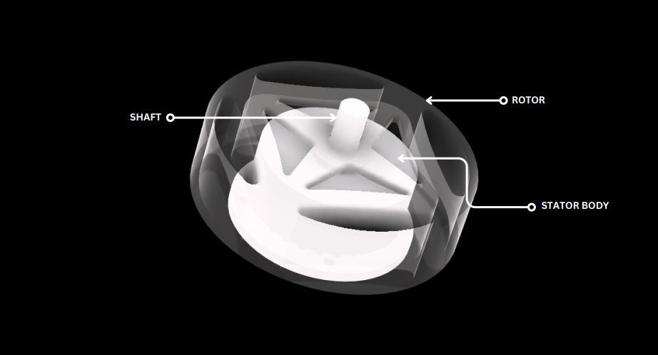
An internal stator and an external rotor make up this actuator. The stator is made up of soft material, silicone rubber (Ecoflex 00-30) and has pockets along its circumference whose expansion and contraction can be regulated by pressurized air. The rotor is a rigid body with internal spikes arranged in accordance with the stator pockets. The stator and rotor are mounted to a common shaft.
The expansion of the stator pockets pushes the spike of the rotor, causing a rotational motion about its axis. Increasing the number of pockets reduces the step angle and thus improves the accuracy. The pressurized air is supplied using solenoid valves controlled by an Arduino. The Arduino can be coded to control the inflation and deflation times of the pockets as well as the number of steps taken by the rotor.
Static Structural Analysis
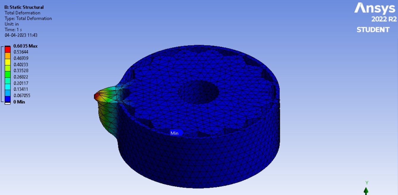
A model of the stator with 16 triangular shadped pockets was created and static structural analysis was performed in Ansys using the material properties of ecoflex-030. The purpose of this analysis was to evaluate the behavior of the material. The results of the analysis, as shown in the figure below, were obtained by subjecting the stator to various pressures to assess its behavior. The analysis yielded the desired results, enabling us to proceed with the use of this material.
Prototype 1
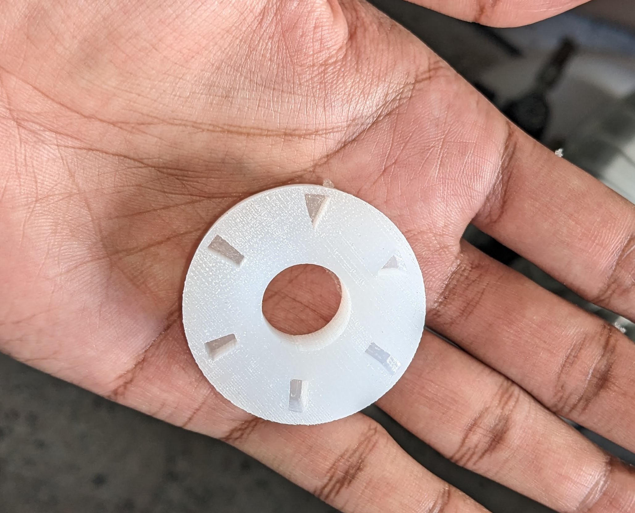
The first prototype focused on choosing the best pocket shape to achieve the most expansion. This pattern featured six pockets, with three different shapes - triangular, rectangular, or trapezoidal - and two wall thicknesses - 1mm and 2mm - for each.
Fusion 360 was used to build the stator’s initial design. The stator needs a mould to be poured into so that it can cure because it is comprised of soft material. A mould was developed around the stator’s design. In order to achieve the necessary hose holes and pocket holes, this mould was constructed from a base and a lid. The idea was to fuse them together by setting the partially-cured stator lid on a fully-cured stator base.
The moulds were 3D printed. Ecoflex 00-30 solution was prepared and first poured into the base mould. It was left to cure for 4 hours, and then the fresh solution was poured into the lid mould. Once it was semi-cured, it was placed on a stator base. A simple pneumatic circuit was constructed to provide pressurised air into the pockets. Each pocket was tested with varying ranges of pressure, and the expansion was closely observed.
Conclusions from Prototype 1
Trapezoidal pockets with thin walls gave the maximum expansion at mid-range pressure. The exact semi-curing time needs to be determined so as to ensure the perfect setting of the base and lid. Support is needed at the centre to align the base with the lid exactly. Air bubbles in the stator body are to be avoided.
Prototype 2
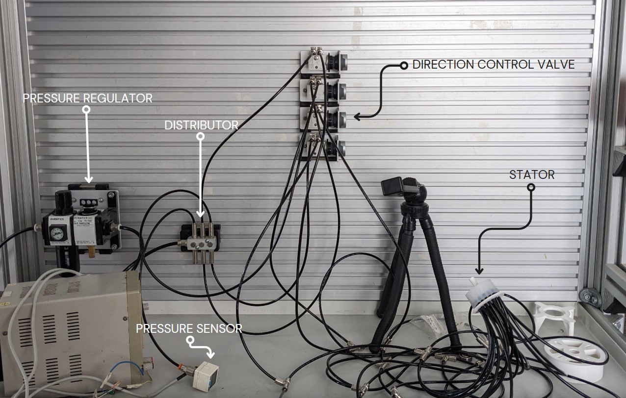
A shaft that ran through the middle of the second prototype made it easier to align the base and lid. Moreover, this assembly setup made easy demolding possible. 16 1 mm thick trapezoidal pockets made up this stator’s structure. A rotor with four internal spikes was created, and 3D printed. The idea was to inflate four pockets at a time so that each one pushed one spike of the rotor before the process was repeated with the following set of four pockets. To accomplish this, four 3/2 manually driven directional control valves were installed into a pneumatic circuit, one for each of the four pocket sets. The pockets were then linked to the switches using 4 mm hoses and tested for expansion. Experiments were carried out to determine the exact inflation and maximum pressure the pocket could withstand.
Conclusions from Prototype 2
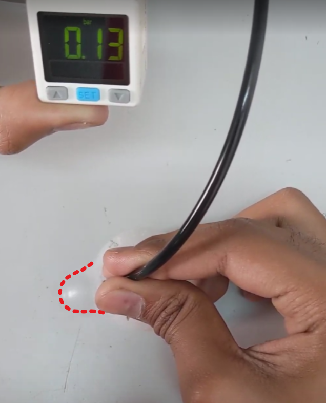
Trapezoidal pockets offered extremely good inflation even at a low pressure (pocket busted at 0.05 bar pressure generating inflation of 29 cm). Little air bubbles were still present in the stator, which led to an unequal expansion of the pockets. A method must be determined to get rid of these bubbles when pouring the solution. Rotor spikes should be made almost tangential to the shape of inflated pockets, which will result in a normal force on spikes giving a better push.
Final Model
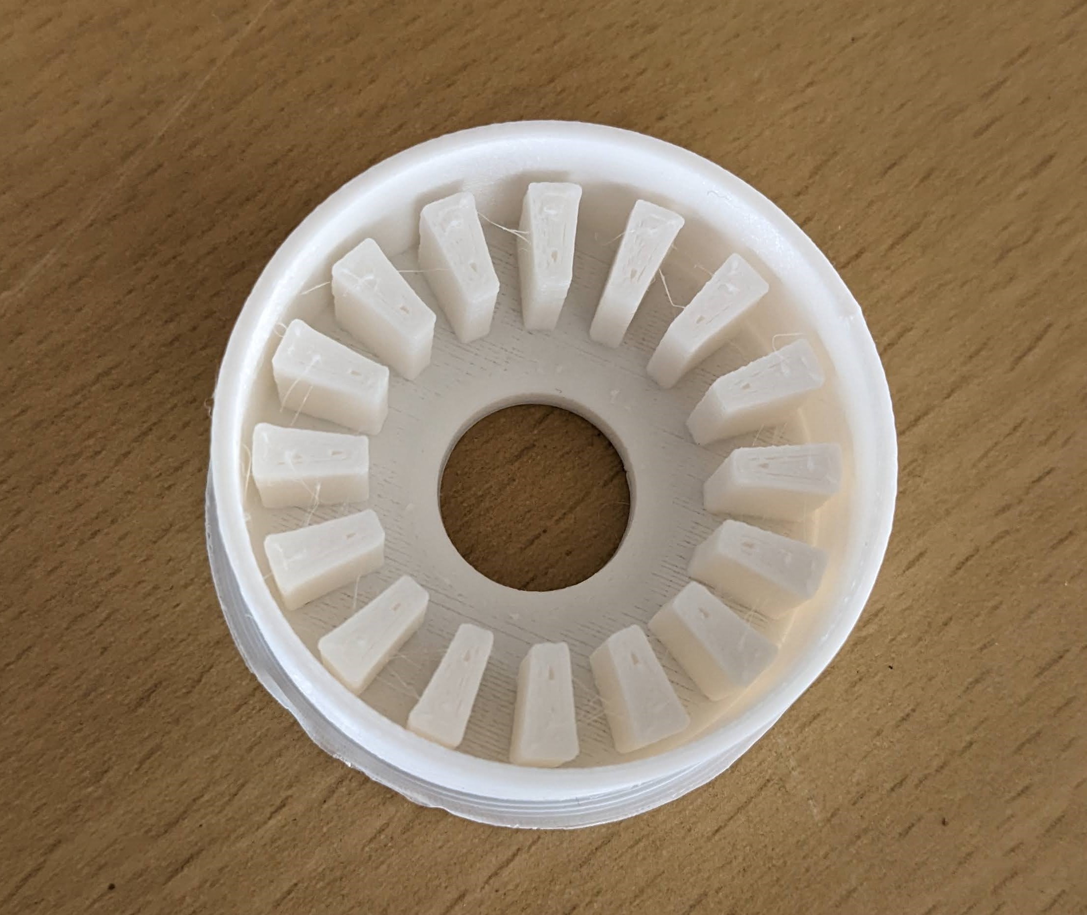
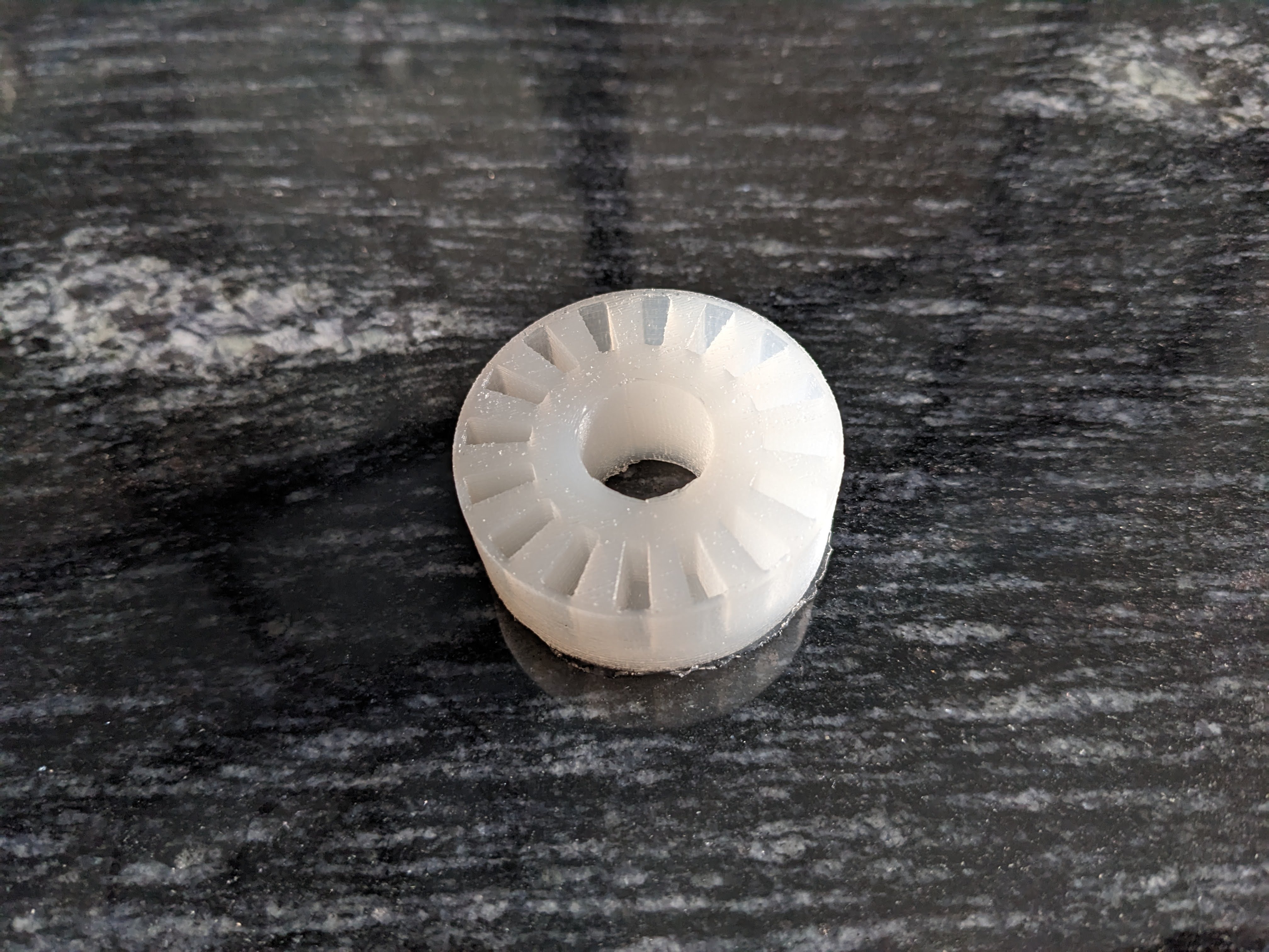
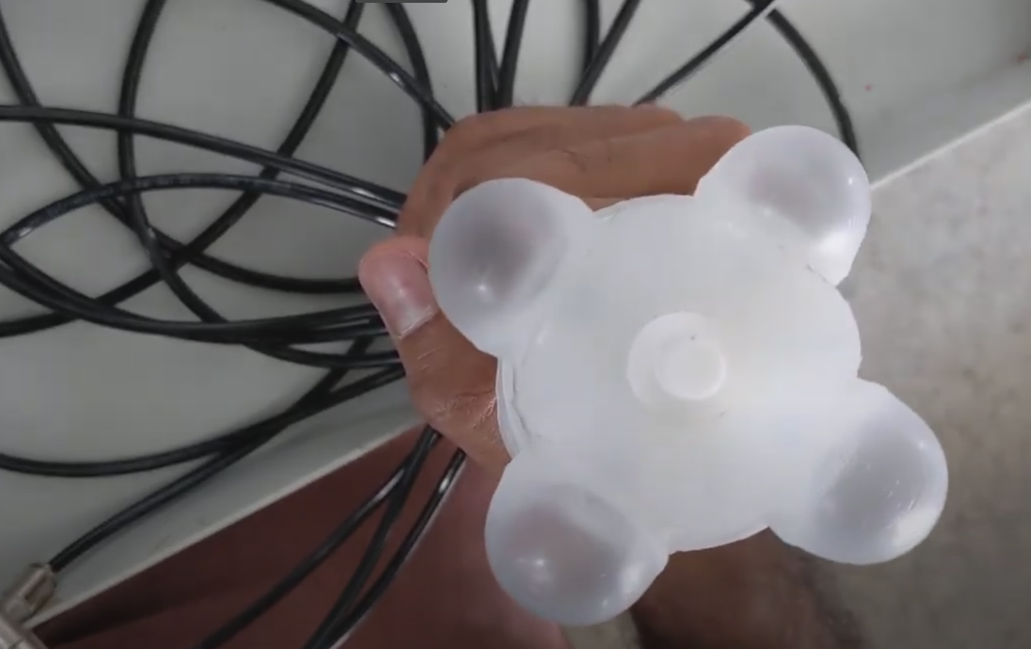
This design comprised a stator with 24 identical trapezoidal pockets. The base, wall, and lid were the three components that made up the stator mould. The air bubbles on the outside walls of pockets could now be removed - thanks to the wall’s ability to rotate on the base. In order to prevent extremely tiny air bubbles from affecting pocket expansion, the wall thickness was increased to 2mm. To ensure better push, a rotor with an interior convex spike-like structure was created, and 3D printed. The pneumatic circuit now had to be made simpler as the number of pockets increased. To do this, a hose connector was created, and 3D printed.
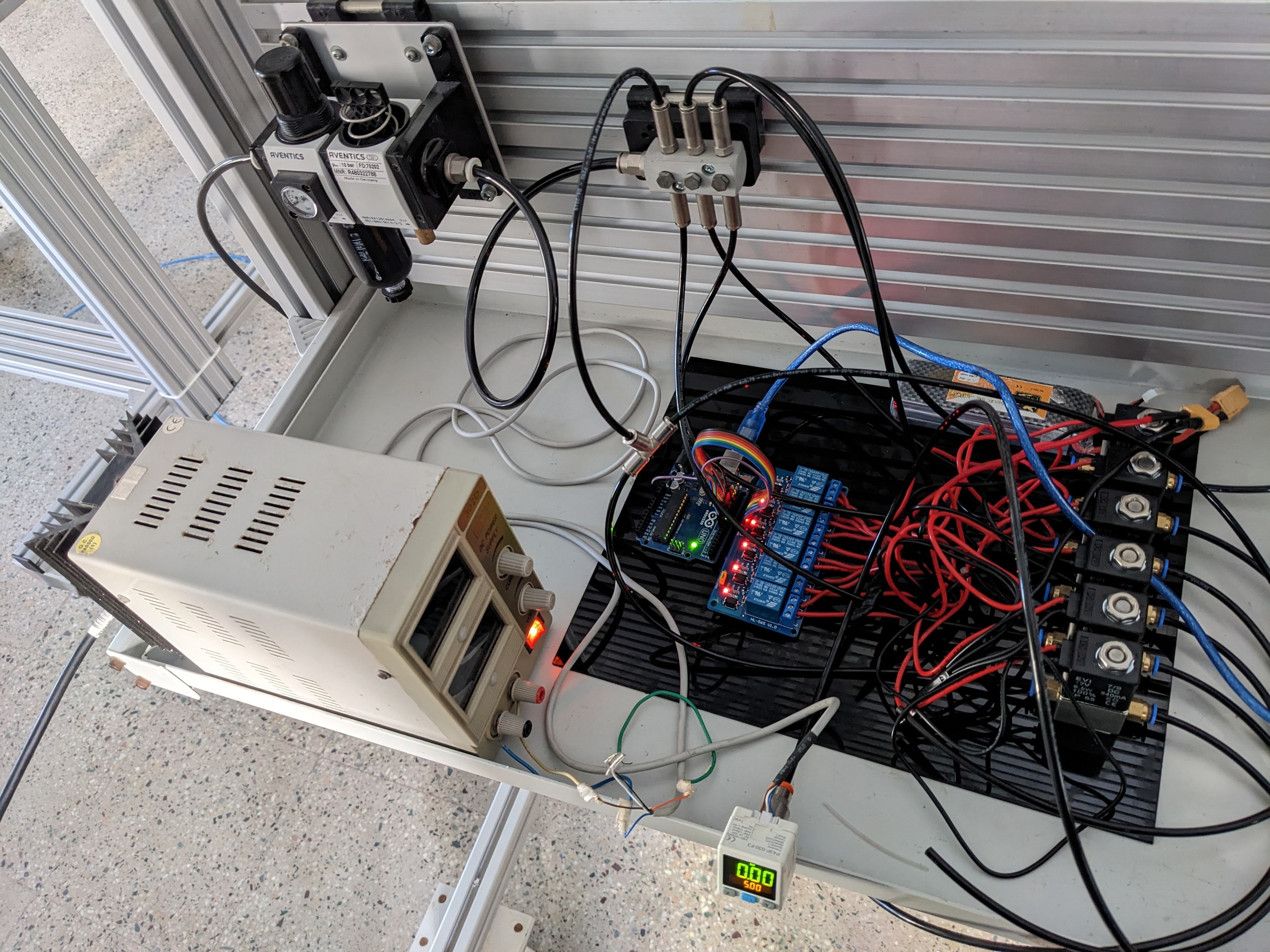
We used solenoid valves to automate the procedure because an Arduino can control them. Relay modules were used to transition between high and low voltages. The image below displays the circuit schematic for the relay module with a single channel. We have a 6-channel relay module in our setup. To sum up, a relay module was connected to the Arduino and to 12 V solenoid valves. This allows us to control the inflation and deflation times of the pockets by varying its parameters in the Arduino code.
Results and Conclusion
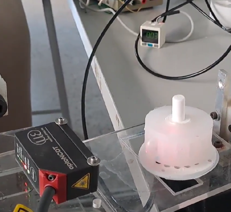
Accuracy of 360/24 = 15 degrees per step by using 24 pockets was achieved in the final model. Tracking and regulating the motor’s rotational steps through the usage of solenoid valves increases its potential in industrial applications.
Working with silicone rubber material, which is less explored in the field of industrial applications, gave insights into its potential due to its flexible nature. A few examples of this material in industries are motors being replaced by soft motors, rigid links being replaced with soft links etc. This material can also be used to achieve biomimicry.
Future improvement of this project
The accuracy can be increased further, although it requires accurate analysis. The speed of rotation can be increased by optimizing valve opening timing. Rotor can be optimized not only to reduce weight and size but also to give a better push. The silicone rubber material is new to industrial applications, and not many of its properties and behaviours are known. This model can be tested under various conditions to determine their properties which further increases its scope.
References
This Project was inspired by
- “wheeled_robot_with soft_rotary_motors”
- “Rotary Actuators Based on Pneumatically Driven Elastomeric Structures” X. Gong, K. Yang, J. Xie, Y. Wang, Y. Wang, P Kulkarni, A. S. Hobbs, and A. D. Mazzeo