Mentors:
Launnish Gaurangee
Members:
Rohan Abhilash Ahan Prasannakumar Shetty Kushal Gowda Anurag Kumar
Aim:
This project aims to build a prototype of self balancing robot using gyroscopic, accelerometeric sensors and stepper motors using a closed loop PID algorithm programmed by Multiwii software.
Introduction:
Self balancing robots have a lot of real time applications as in self balanced scooters to UAV(Unmanned Aerial Vehicles).This project will be solely focused on building a self balanced robot using steppers and MPU6050 sensor using Arduino Nano as microcontroller for closed loop PID configuration and Multiwii for programming.
Peripherals:
Nema-17:
Stepper motors are step controlled DC motors which are controlled by motor driver IC’s for step synchronisation. NEMA-17 steppers coupled with bipolar A4988 IC controlled at full step(1.8° step angle or 200 steps/revolution) have been used with low speed high torque configuration.As 2 steppers are employed AccelStepper library is used to synchronise the motors for fine operation. The main reason stepper motors are used against other motors(preferably PMDC motors) is because steppers have fine angle resolution and high holding torque which is one of the major requirement for this model.
MPU6050:
MPU6050 is a 6 axis accelerometer and gyroscope sensor used to measure accleration along 3 axis and angular rotation along 3 axis. This forms the heart of this particular model as the microcontroller gets the angular rotation from this module and accordingly triggers the stepper IC’s to control the accleration of the stepper motors to balance the error angle from mean position.
HC-05:
HC-05 is a bluetooth module operating at(2.4-2.5GHz) and has a signal range of 10m. As multiwii has android app capability, we can use it to control the model using our smartphones using bluetooth seamlessly.So this bluetooth module needs to be configured as “slave” operating at 115200 baudrate to communicate with the mobile.
Arduino Nano:
This serves as the microcontroller to collabrate all the above mentioned peripherals using PID algorithm and work in synchronised manner. All the peripherals needs to be connected with the microcontroller as shown in circuit diagram on a universal PCB and soldering lead paths can be used for pcb prototyping.
Lipo battery:
This model particularly requires lipo battery to power up this model as the stepper motors are rated at (0.8-1A) which at most requires a discharge current of 2A(max) which can’t be obtained from a 2200mAh li-ion battery and a li-po battery needs to be employed.This model boasts a 12V, 2200mAh 30C(30A discharge current) lipo battery for an operation period of 1.5hrs(approx).
Algorithm:
The main working principle of this model is the use of PID algorithm to balance the robot at steady state.Initially the real time angular displacement and accleration is maeasured by the mpu6050 module which are converted to digital signals and sent into the PID loop. The PID algorithm has three components P-Proportional, I-Integral and D-Derivative entities.
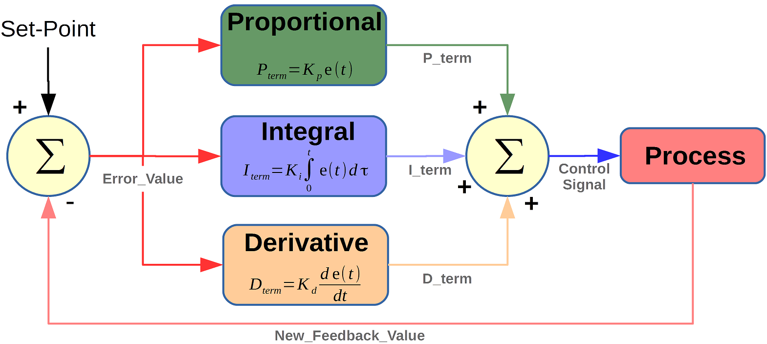
Proportional- This gives an output that is proportional to current error. It compares the desired
or set point with the actual value or feedback process value. The resulting error is multiplied with a proportional constant Kp to get the output. If the error value is zero, then this controller output is zero.
Integral- It integrates the error over a period of time until the error value reaches zero. It holds the value
to the final control device at which error becomes zero.The speed of the response is increased by decreasing integral gain, Ki.
Derivative- This predicts the future behavior of the error. Its output depends on the rate of change of error with respect to time,
multiplied by derivative constant. It gives the kick start for the output thereby increasing system response.Increasing the derivative gain Kd increases the speed of response.
The processed values by Kp,Ki and Kd are sent to the microcontroller and the necessary signals are sent to the steppers to balance out the prevailing error and balance out the model to steady state value.
Software implementation:
The above proposed algorithm is integrated with the peripherals using multiwii module in arduino ide and the necessary code has been written and calibrated for fine operation of the model.EZ-GUI app in the smartphone gives the necessary UI for fine controlling of the model and the pid values needs to be calibrated in this app that suits the model.
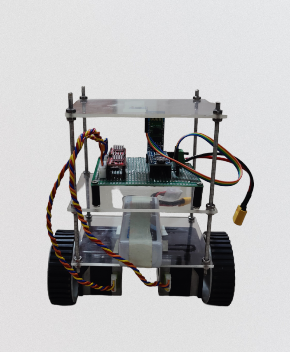
Hardware setup:
This is the most important aspect of this model and most self balancing models fail to balance due to improper load balancing and varying center of mass. So as far as this model is concerned the hardware structure needs to be intact with enhanced protection to vibrations as stepper motors cause highly impulsive vibrations at low speed and high holding torque conditions and the centre of mass needs to be equally balanced between the compartments. The MPU6050 module needs to be placed at the top most location for detecting small angle changes and decreased reaction time of the model.The wheels needs to be uniformly grooved or else at the point of balance the model oscillates and evetually falls.
Calibration:
After the hardware and software implementations are finished the most cumbersome process of calibration for fine tuning the PID values
with respect to model is to be completed.This includes shifting center of mass and tuning Kp, Ki and Kd values for finer operation and the values
changes with respect to the particular model’s hardware setup.First of all, Kp,Ki and Kd values needs to be set to 0. Start increasing the Kp value
until the model stops overshooting the error and starts to vibrate about the steady state error and oscillates about that point.Now, the Ki needs
to be gradually increased and the robot’s reaction time to a small unbalance needs to be matched bringing error to mean position.Finally,Kd needs
tuned so as to counter vibrations and oscillations of the model about the mean position.
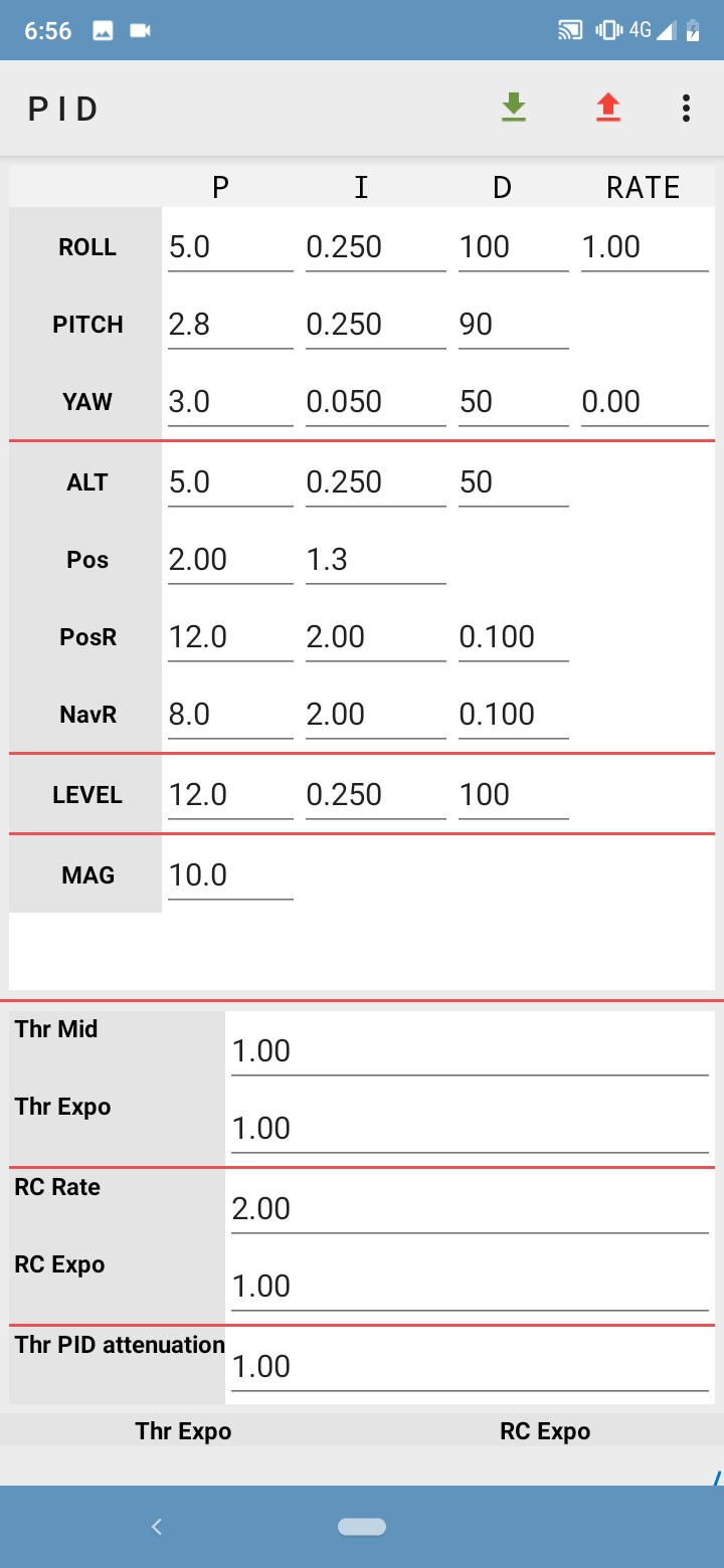
Note: (For Calibration on EZ-GUI app)
Kp(0-20)- A low Kp value does not react to the unbalance and model falls where as a high Kp value overshoots the error and throws the model in the opposite direction so the optimal value to start tuning is about 10.
Ki(0-0.250) - A low Ki value has more reaction time and the robot does not respond to the error instantaneously where as high Ki value creates a lot of vibrations so the optimal value to start tuning is about 0.1.
Kd(0-100) - This doen’t have a optimal value to start tuning so the value can be determined when the model stops oscillating and error vibrations have been eliminated.
Conclusion:
The self balancing robot model was completed satisfactorily and had smooth operation when controlled with the smartphone and balanced efficiently. This model has great applications and can be extended over to make real world self balanced hoverboards or even single wheel balanced rovers for efficiently traversing over compact geographical terrain where a 4 wheeled slambot can’t be used for mapping as this model can remain stable about the mean position at any angle and even the accleration capabilities of this models can be increased.Therefore this model has a wide range of applications and can be extended to different domains.
References:
- https://electricdiylab.com/diy-self-balancing-robot/
- https://lastminuteengineers.com/mpu6050-accel-gyro-arduino-tutorial/
- https://lastminuteengineers.com/a4988-stepper-motor-driver-arduino-tutorial/
- https://www.elprocus.com/the-working-of-a-pid-controller/