Project Mentors
- Mallikarjun G M
- Yuvasankar B
Project Members
- Kishlay Singh
- Kshamaa Acharya B
- Himanshu Garud
Introduction
The pneumatic motor works on compressed air only and no fossil fuels are required. We store compressed air in a cylinder, which holds some useful energy within it. This energy can be utilized for useful purposes. When this compressed air expands, the energy is released to do mechanical work, which may be rotatory or linear.
Objectives
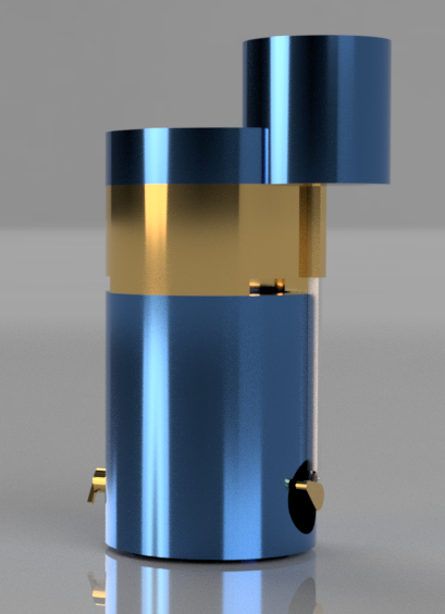
This project aimed to design a pneumatic motor, which works only on pressurized air. This motor has a speed of 400 rpm and can withstand a high pressure of 830188.9117Pa.
Methodology
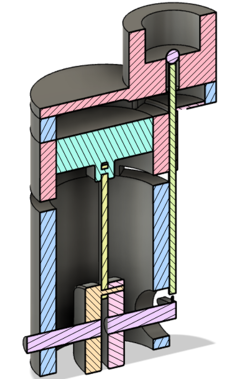
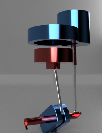
The overall model contains two basic mechanisms;
- Crank Shaft Mechanism: It is the main mechanism of the model. It consists of a piston connected to a connecting rod. The other end of the connecting rod is connected between two rotating cranks away from their centre. This converts the translation motion of the piston to the rotational motion of the crank.
- Push-rod and roller cam: The rotating rod connected to the cranks, on the back end has the push-rod. The push rod has a roller at the bottom end which rolls over the rotating rod. The push rod extends to the top into the inlet valve. The rotating rod below the roller has a non-circular design which moves the push rod up at a desired time and position.
The complete cycle starts when the inlet valve opens. As it opens pressurized air fills into a chamber above the piston. As enclosed air exerts equal pressure in all directions, the piston is forced downwards. As the piston moves down the crank is rotated. Just above the bottom dead centre of the piston are the outlet valves. The pressurized air mover out through it. The momentum of the rotating crank pushes the piston back upwards. Just before the piston reaches back to the top dead centre the push-rod moves up opening the inlet valve again and the cycle repeats.
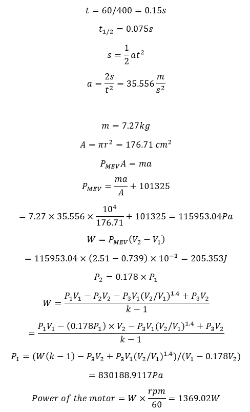
Calculations
t = time required to complete one cycle of rotation
t(1/2) = time required to complete half cycle of rotation
s = stroke length
a = acceleration of the motor
m = mass of piston and the rod
A = Area of the piston
P(mev) = Mean effective Pressure
W = Work done by the motor
P1 = Pressure of air at the inlet
P2 = Pressure of air above the piston just before outlet valve opens
P3 = Pressure of air at the outlet
V1 = Volume of pressurised air above the piston
V2 = Volume of pressurised air after expansion
Conclusions
The model designed by us is a small-scale working model of the pneumatic engine. This model has various advantages as compared to the conventional model which uses fossil fuels. Main advantages being :
- Zero emission.
- Use of renewable fuel.
- Zero fuel cost (the cost is involved only in the compression of air).
Need of a pneumatic motor
Pneumatics has long since played an?important role?as a technology in the performance of mechanical work. It is also being used in the development of automation solutions.
- Efficient – The atmosphere contains an unlimited supply of air for the production of compressed air, which can be easily stored in large volumes. Not only can compressed air be easily transported through pipes but after it’s been used it can be released directly into the atmosphere without further processing.
- Reliable – Pneumatic systems are extremely durable and reliable. Compared to electromotive components, pneumatic parts are proven to last longer and require less maintenance.
- Simple – Pneumatic system components are relatively simple, which makes them suitable for less complicated automatic control systems. You can choose from a choice of movements, including linear or angular rotational movement, coupled with continuously variable operational speeds.
- Safe – Pneumatic systems can work in inflammable environments without the risk of fire or explosion. Unlike electromotive components, pneumatic system components do not overheat when overloaded and are therefore less of a fire hazard.
- Economical – Pneumatic system components are relatively inexpensive, making the initial outlay for pneumatic systems very cost-effective. Furthermore, because pneumatic systems are so durable and reliable, maintenance costs are significantly lower than with other systems.