Mentors
- Vedangi Nis hane
- Siddalingeshwar S P
Members
- Priyanshu
- Sarthak
Aim
To design and understand the dynamics of gliders and perform Ansys CFX simulation on different airfoils to get the most desirable one for an efficient glider having extended period of flight.
Introduction and Overview
Gliders are a popular small scale aircrafts that are widely used in domestic and international purposes. These aircrafts are categorized as fixed wing, RC gliders and self launched and many more. These gliders also have a high glide ratio that would give them a long flight time, another important aspect being the weight of gliders as a higher mass would give a not so efficient flight time and height.
In this project we would design a simple glider of wing span 400mm,length 300mm and dihedral angle of 4 degrees. The model would be designed in Fusion360 considering a fixed wing glider and followed by the analysis of the airfoil used to make the wing of this glider based on the velocity, pressure, and coefficient of lift and drag. The coefficient of lift and drag play a key role in the flight of gliders which would be calculated and would be used to come to a conclusion.
Technologies used
-
Fusion 360: A cloud based 3D CAD/CAM software that is extensively used by engineers to create and modify 3D models, simulate their functionality, and generate toolpaths for manufacturing.
-
Ansys Fluent: An analysis software widely used post the modeling part to optimize product performance and to test it based on real life conditions.
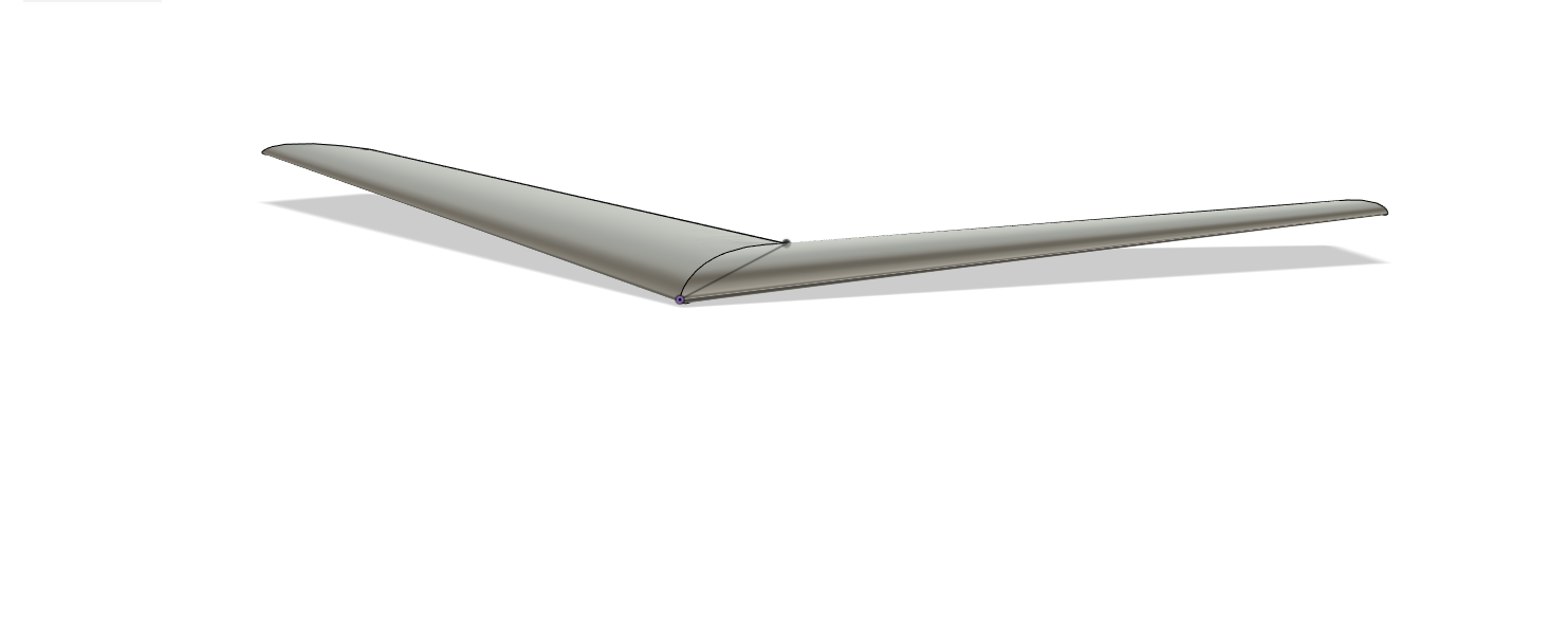
Modeling
Different e-series airfoil designs for the glider with a wing span of 400mm, length 300mm and dihedral angle of 4 degrees were modeled in Fusion360. The geometric models were compared by varying the shape of the airfoil and the angle of attack(alpha).
The Fusion360 model was then exported to Ansys Fluent in .step format and CFD Analysis of the designs were carried out.
Analysis
In the simulation work, we have studied the laminar flow analysis of air-fluid for AG 24 airfoil through Ansys Fluent to simulate the values of pressure and velocity of air-fluid. During the study, the coefficient of lift and drag, the velocity of the upper surface, and the pressure of the lower surface of air-fluid for the airfoil are determined for different angles of attack. The Fusion360 geometry of the airfoil was first imported in the Ansys Design Modeler. The enclosure of 3 m, 2 m, 2 m, 3 m, 2 m, and 2 m lengths respectively has been drawn to get a better result of fluid moving around the symmetrical surface of the airfoil. Further the airfoil’s shape was meticulously meshed for accurate simulation. All the parts of the airfoil are specified in the meshing step while CFD meshing was used. The inlet, outlet, and walls of the airfoil are named in this step. The geometry of the elements and nodes is maintained in a triangle form, and the meshing configuration includes medium smoothing, coarse relevance center, and these features. The next step is the solution setup. In this step, we select the fluid which is air here, and the k omega sst model for the flow of air-fluid to get better results from the simulation. In boundary conditions, the inlet is taken as inlet velocity with an initial value of 12 m/s and outlet as outlet pressure. Pressure-based Ansys Fluent solver, absolute velocity formulation, and steady time are used in solution setup to perform the calculation. Then we determined the coefficients of lift and drag forces in the report definition process by creating their respective names and selecting the airfoil wing portion only. Finally, we initialized the all-zones values.
Results
The ansys simulation gave the results for coefficient of lift and coefficient of drag, pressure and velocity contours along the airfoil for a set of iterations.
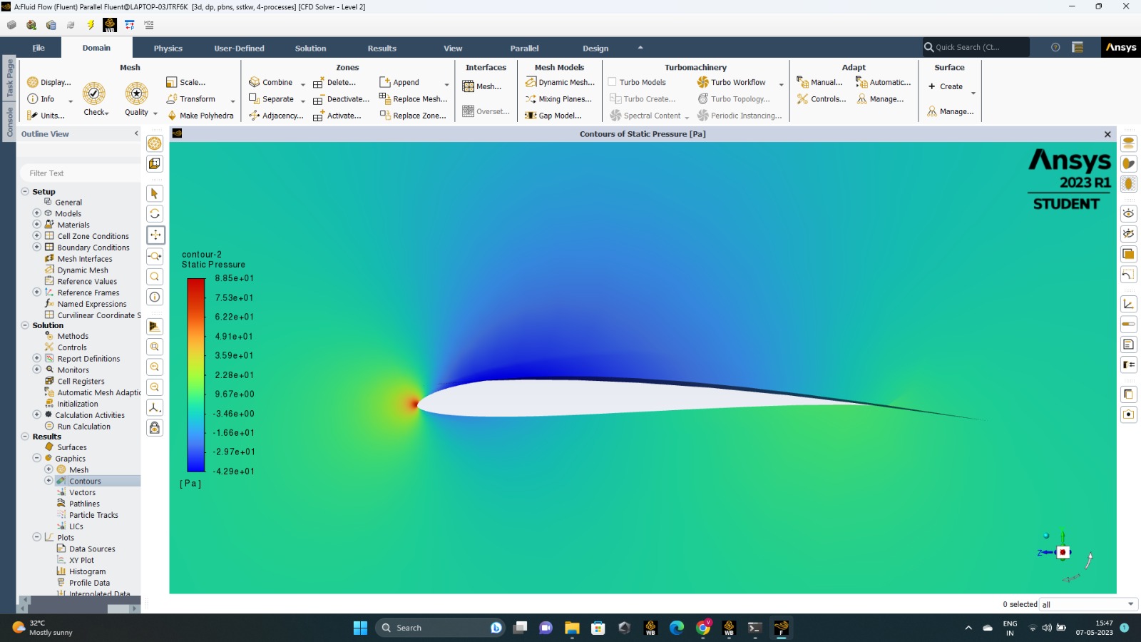
AG 24
The pressure contours came out as shown. High pressure was found on the lower end and low pressure on the upper surface of the airfoil, the tips of the airfoil had the highest pressure.
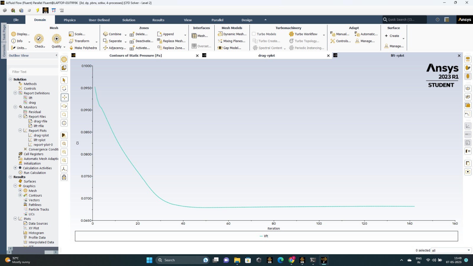
 The coefficient of lift reduces from a higher value to a constant value as the number of iterations increases.
 The coefficient of drag increases from a lower value to a constant value as the number of iterations increases.
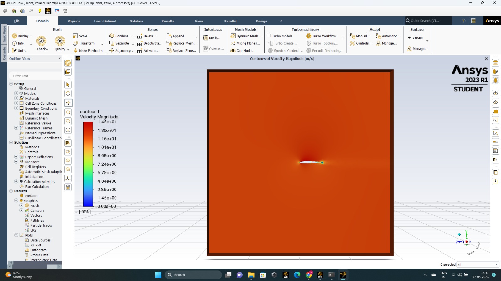
 The velocity contours were observed as shown.
Conclusion
In this project, we have understood the modeling of simple gliders and analysis of airfoils that would be used in gliders. The e airfoil gave the most desirable results based on the pressure contours and coefficient of lift.