Project Mentors
- Ekta Ramnani
- Impna V A
Project Members
- Diptesh Banerjee
Abstract
Jet Engines play a vital role in the aviation industry; hence, their performance is significant. The turbine blades of jet engines have a unique airfoil shape which creates lift force and makes them turn. A new design method was used to improve turbine blades’ performance, originating from the fins on a humpback whale. Various simulations were undertaken using ANSYS CFD to investigate the influence of the tubercle leading edge on a linear turbine cascade’s aerodynamic performance.
Aim
This project aims to design the baseline blade and blade with leading-edge tubercles, and compare the performance of the baseline blade with the tubercled blade. The simulations were carried out for various angles of attack to compare the behavior of baseline and tubercled blades.
Methodology
Design of Blades
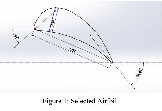
The airfoil coordinates were taken from the research paper [1] as shown in figure 1. The chord length of the selected airfoil is 1.09m and the camber percentage is 35.
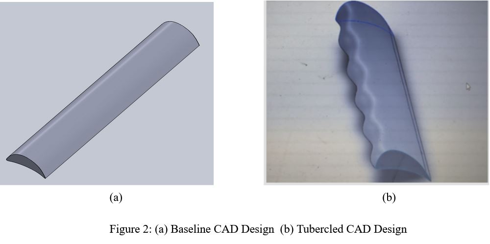
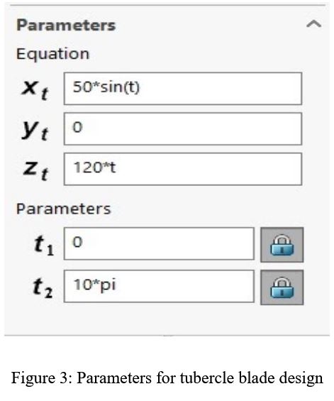
The designing of the CAD models was done using SOLIDWORKS. The difference between baseline and tubercled blade design can be seen in figure 2. On the leading edge of the normal blade, a sinusoidal wave of amplitude 50mm was imposed for which the parameters are as shown in figure 3. The length of both blades is 450mm.
Geometry
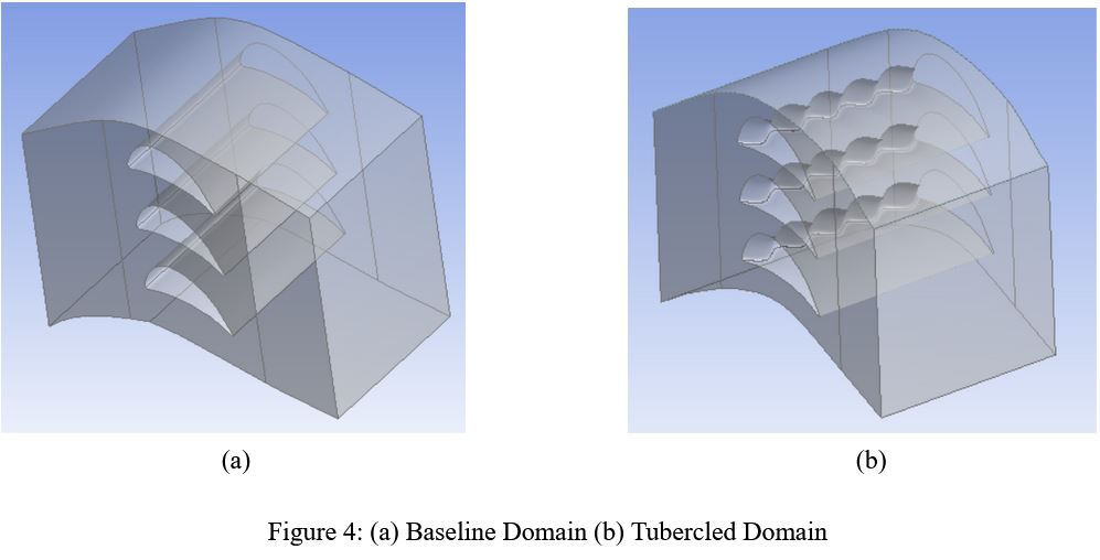
The domain of the normal and tubercle blade was chosen as shown below:
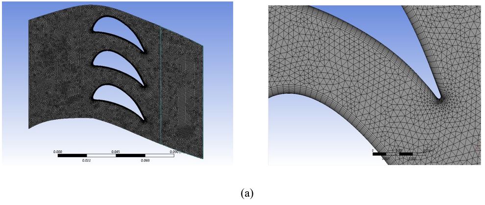
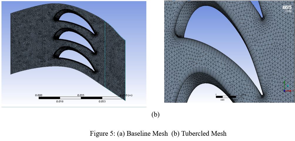
Mesh
The meshing of the normal and tubercle blade was done using the Patch Conforming Method(tetra) and inflation of 0.0015mm total thickness with a growth rate of 1.2 was used. The number of elements in the normal and tubercle blade domain was almost 23 lakhs and 26 lakhs respectively. A grid independence study was carried out to decide the minimum number of elements required for the domain that would not affect the results on increasing the number of elements.
Simulation
The Spalart Allmaras turbulent model was adopted and coupled solver was used. The hot incompressible air was considered as the working fluid. The initial conditions were set as shown in table below (Table 1).
Initial boundary conditions
| Boundary conditions | Values |
|---|---|
| Inlet Velocity | 300 m/s |
| Inlet temperature | 1100 K |
| Operating Pressure | 101.325 kPa |
| Initial Gauge pressure | 398.675 kPa |
| Air density | 0.26156 kg/m^3 |
| Dynamic Viscosity | 5.0242e-05 kg/m*s |
| Kinematic Viscosity | 1.9772e-04 m^2/s |
| Prandtl number | 0.73036 |
The simulation was done for different angles of attack varying from 0 degrees to 35 degrees with the same initial conditions as mentioned in Table 1 to study the results.
Results
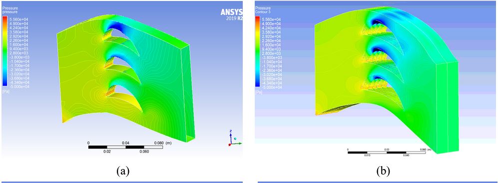
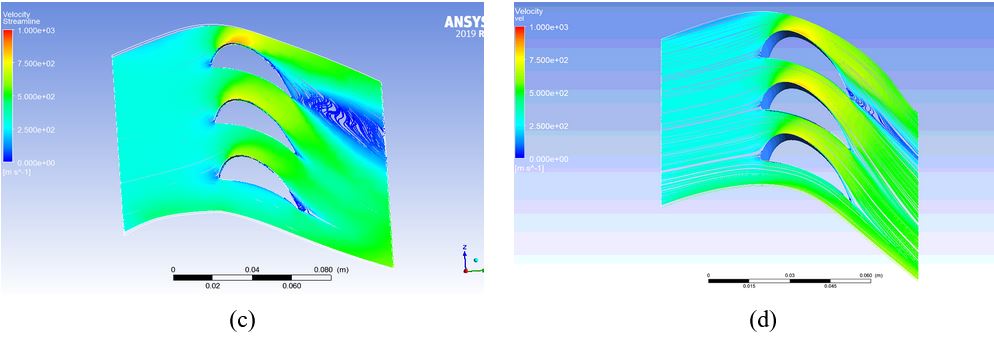
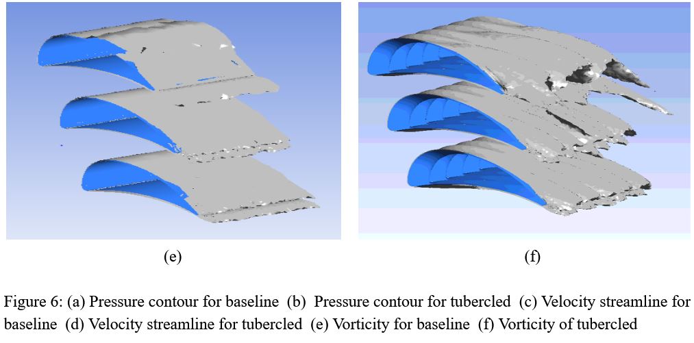
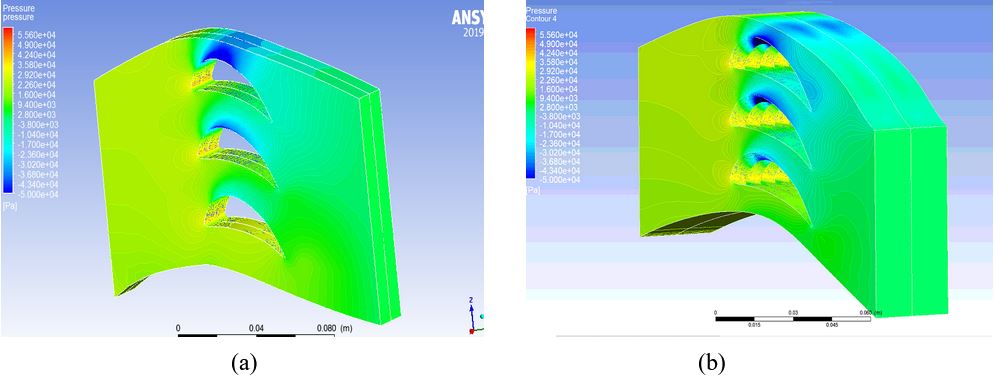
The below results are obtained for 10 degrees of angle of attack:
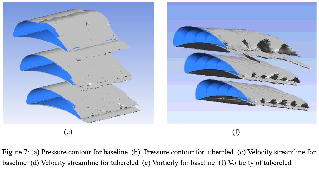
The below results are obtained for 20 degrees of angle of attack:
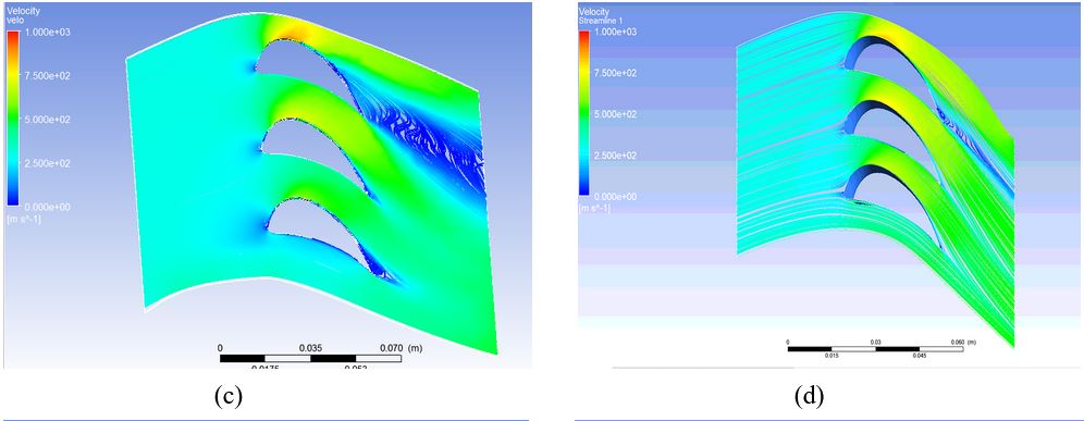
 From figures 6c, 6d, and figure 7c, 7d, it is evident that flow separation in tubercled blades has reduced as compared to baseline blade. This is because the tubercled blade generates secondary flows as shown in Figures 6(f),7(f) which delays the flow separation. The secondary flow occurs due to the vortices that are generated at the tubercle leading edge.
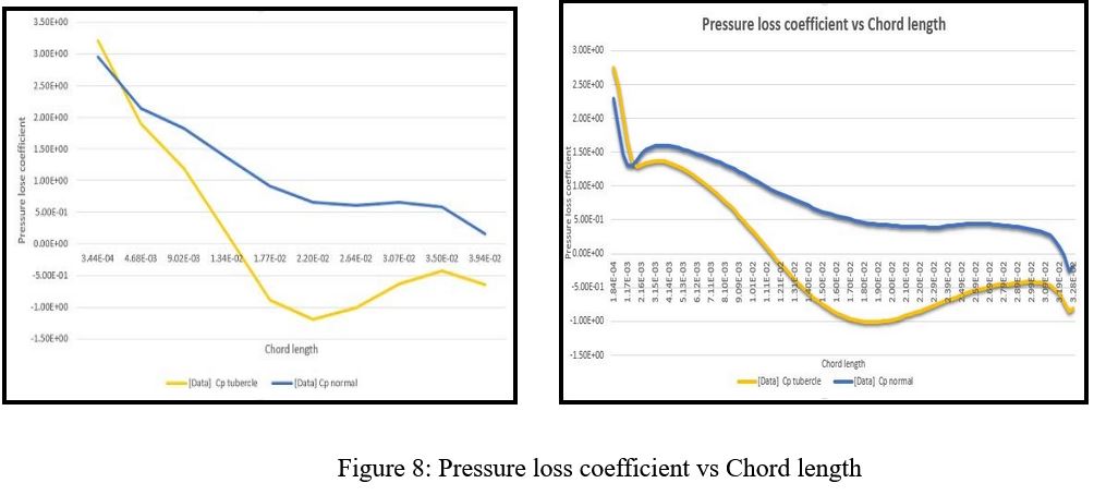
The below graphs are obtained for 0 degrees (left) and 20 degrees (right) of the angle of attack. It can be inferred from the graph that the pressure loss coefficient for tubercled blades is lower than the baseline (normal) blade.
Conclusion
- The tubercled blade has less flow separation as compared to the baseline blade [Figure 6c, 6d, 7c, 7d], this is due to the fact that tubercled blades generate vorticity [Figure 6f and Figure 7f] which delays the flow separation. This advantage allows the tubercled blades to be stacked nearer to each other, expanding its application in compact sizes too.
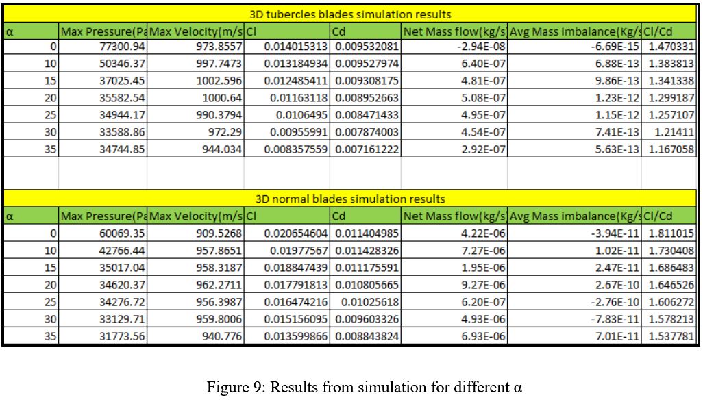
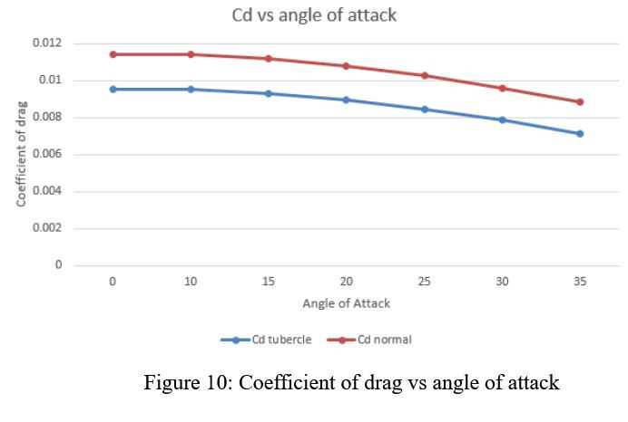
- From figure 10, it can be inferred that there is a reduction in the drag coefficient of the tubercled blades, hence tubercled blades can be used in applications where less drag is needed but with the compromise to the lift generated.
- The pressure loss in tubercled has reduced, which can improve the aerodynamic performance of the cascade. [Figure 8]
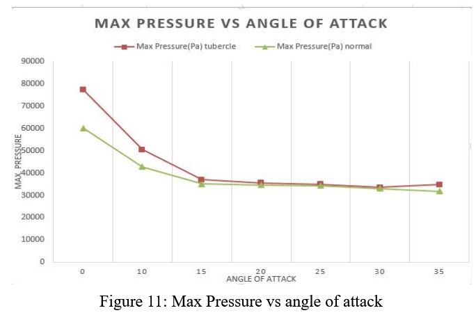
- With the increasing angle of attack, the maximum pressure of both the baseline and tubercle blade becomes equal[Figure 11]
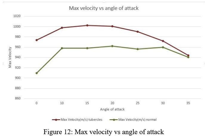
- The main objective of the turbine is to provide a maximum velocity outlet, from figure 12 it is evident that the maximum velocity reached by the tubercle blade is higher than that of the baseline blade. Hence, using the tubercle blade provides maximum velocity which in turn increases the efficiency of the turbine cascade.
Future Scope
- Tapering and twisting can be provided in the blades along with a radial arrangement.
- The change in aerodynamics performance of the tubercled blades can be explored by changing the amplitude and phase of the equation.
- The introduction of end walls in the design can help in studying the end wall losses which is very much evident in turbine blades and also affects their efficiency.
- Stator and rotor blade arrangement can be used to study the power and efficiency of the system, with tubercles imposed on the leading edge of the rotor blade.
References
- GAS TURBINE ENGINE TURBINE BLADE AIRFOIL PROFILE. (2014). INTERNATIONAL APPLICATION PUBLISHED UNDER THE PATENT COOPERATION TREATY (PCT) 1–31. Link
- Kai, Z., & Jun, H. (2019). Investigation on Performance of Compressor Cascade with Tubercle Leading Edge Blade. Baofeng, 1–9. Link
- Saravanamuttoo, H. I. H., Rogers, G. F. C., Cohen, H., Straznicky, P. V., & Nix, A. C. (2017). Gas Turbine Theory. Pearson.
- Dixon, S. L., & Hall, C. A. (2014). Fluid Mechanics and Thermodynamics of Turbomachinery. Elsevier.
- UMAMAHESWARARAO, L., & MALLIKARJUNARAO, K. (2015). DESIGN AND ANALYSIS OF TURBINE BLADE BY USING FEM. International Journal of Mechanical Engineering (IJME), 1–8.
- Jose, J., & Prathibha Bharathi, D. V. V. (2017). Advanced Cooling of Gas Turbine Blades with Sodium Liquid and Air. International Journal of Advanced Engineering, Management, and Science, 1–8. Link
- Numerical Simulation of Performance of an Axial Turbine First Stage. (2012). Journal of Aerospace Technology and Management, 1–14. Link