Project Guide
- Hrishikesh Kulkarni
Mentors
- Omkar Patil
- G Chandan Padmashali
Members
- Kaushik Vinayak Kudchadkar
- Kooralla Srinidhi Amuktha
- Nikhitha Mathew
- Suraj Koppad
Aim
To design and implement IOT based Home automation system using ESP32 board.
Introduction
In this project we have implemented a home automation system. In this we have automated four major components of any house: Security, Water system, Light system , Fire alarm using ESP32-Wroom-32 board. Security is automated by smart lock. The water management is automated using an automatic pumping system which pumps water in the tank based on the water level. Light is automated by motion sensing. A temperature sensor monitors temperature and humidity and triggers an alarm on mobile through IOT. All the four modules have automated control using Adafruit IO.
Implementation
Following are the details of each of the four circuits
Smart lock
In smart lock, we lock and unlock door using Adafruit IO on smartphone. Microcontroller is connected to the virtual keypad from which the password is entered. Door is unlocked if the correct password is entered. Servo motor is used as a lock and it is connected to the ESP32 which is connected to the smartphone via adafruit server.
Following is the circuit implemented for smart lock
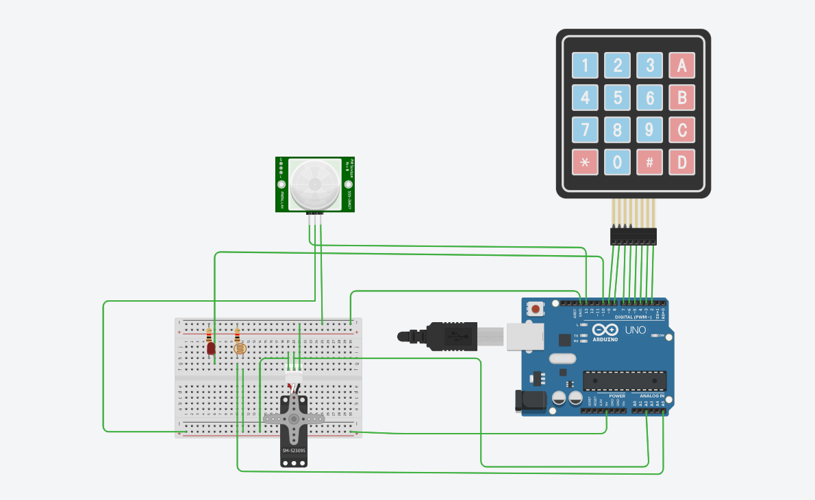
Light control system
Once the door is unlocked the light control system is activated. The LEDs turn on based on PIR motion sensor. We can also switch LEDs connected to ESP32 on and off and also control brightness using a smartphone manually.
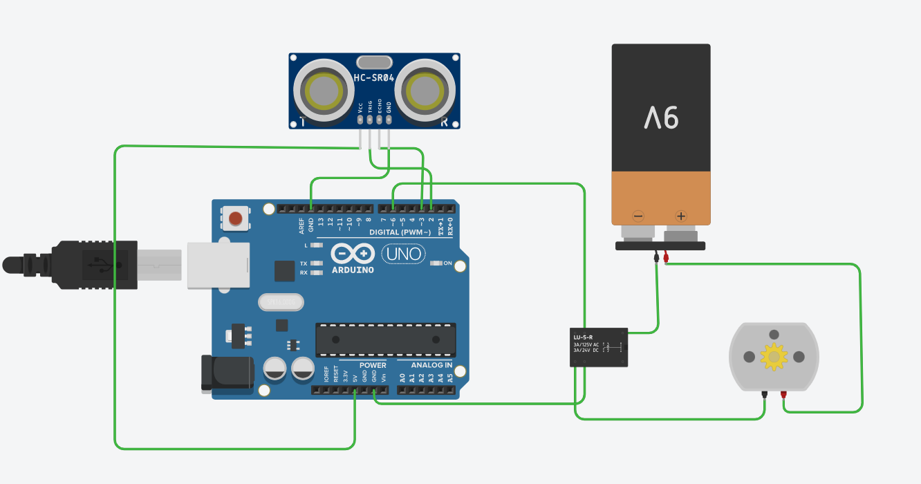
Automated water pump
The water management system uses an ultrasonic sensor HCSR-04 to track water level in the tank and turn on a dc pump if water is below a near empty level and turn off if its above near full level. Water level is indicated on the device. Double channel relay module is used to operate the dc pump.
Following is the circuit of water system
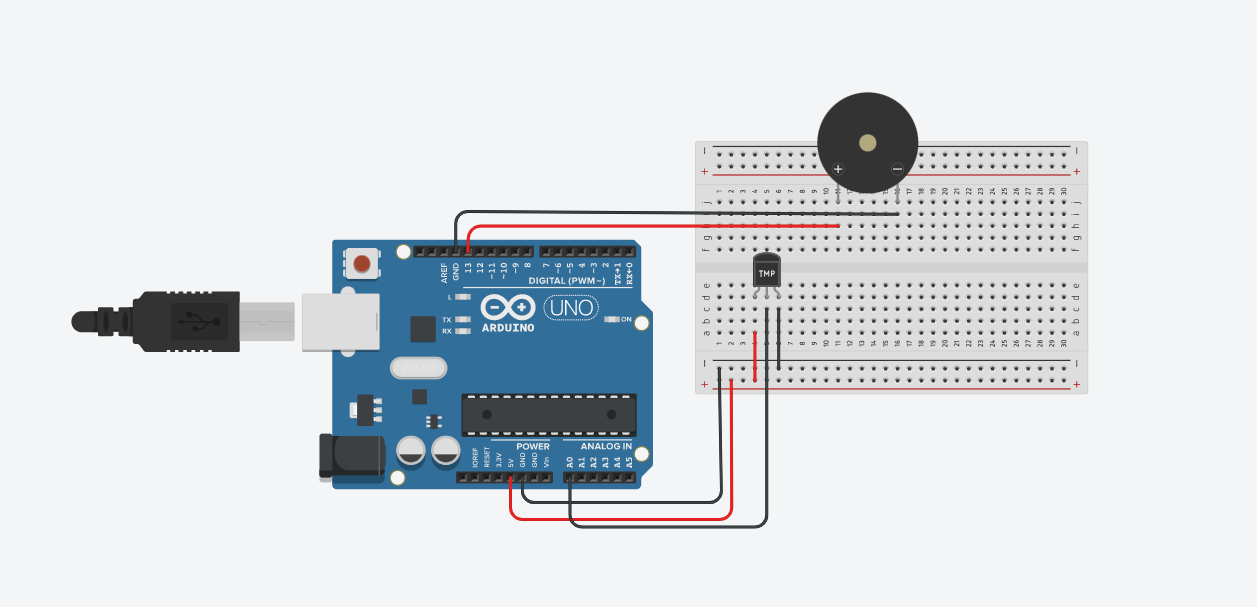
Fire alarm
A DHT11 sensor is used to monitor the temperature, based on which it also alarms the user if temperature levels are high in house. Humidity levels are also monitored and displayed.
Following is the circuit of fire alarm:
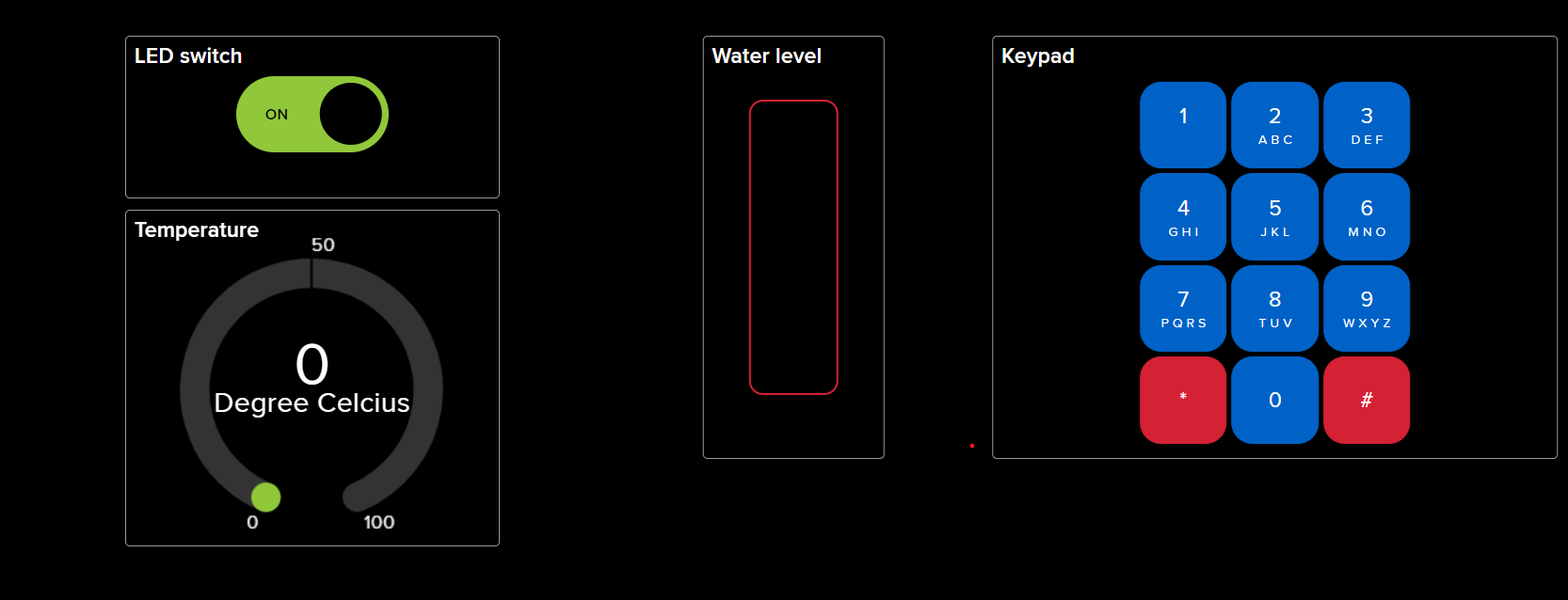
IOT
All circuits are interfaced with Adafruit io through which user can operate and monitor the entire system. Feeds used to control devices:
Conclusion
All the circuits mentioned above have been successfully simulated and implemented. Adafruit IO is used to implement IOT connection. Temperature sensor can be also used to control Fan or Cooler. This system can also be upgraded for AC power supply and to control real life devices using appropriate relay modules or electronic elements.