Project Guide
Professor Dhwanil Shukla, Department of Aerospace Engineering, IIT Bombay.
Project Lead
- Vehan Doshi
Project Members
- Chandran N
- Viba R Udupa
- Mallikarjun G M
Acknowledgements
We express our immense gratitude to Professor Dhwanil Shukla, for his valuable insight during every phase of the aircraft design, and under whose supervision this project was completed.
Introduction
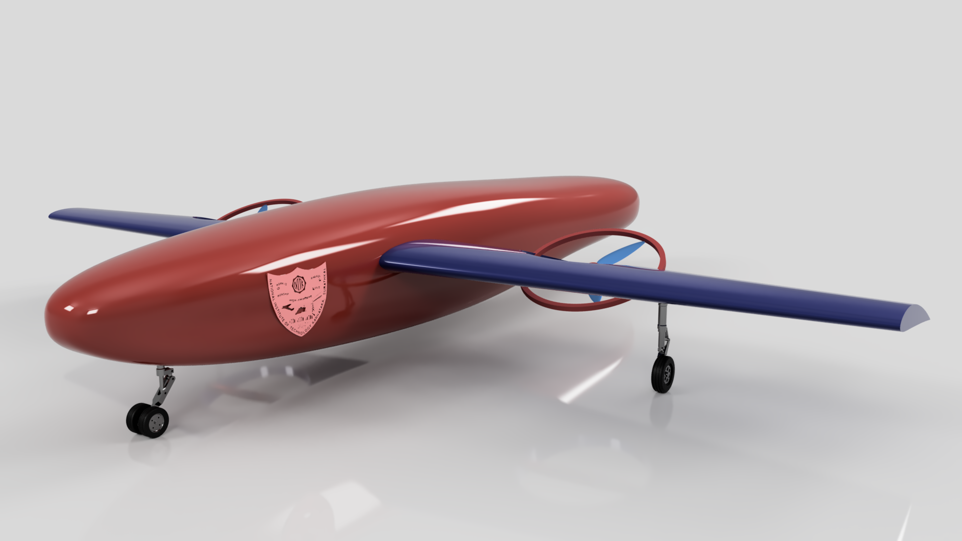
Hybrid powertrains that combine the best of both engines and battery packs are a popular technology that have gained massive attention over the past few years due to growing environmental concerns. They solve the problem of short range battery powered aircraft using an engine in various ways. Employing this technology, a novel conceptual design of a hybrid powertrain is presented that combines the best of both, rotorcrafts and fixed wing aircrafts to obtain a tilt rotor hybrid UAV with fixed wings that has good hover performance with VTOL and increased payload carrying capacity. The design is primarily aimed at helping the military for search and rescue operations during natural calamities and quick supply of goods at high altitude military postings.
Objective
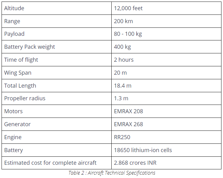
This project aimed to design a hybrid powertrain along with a novel concept design capable of flying at altitudes of over 12000 feet and carry a payload of 100 kg with a range of 200 km and a top speed of 100kmph. The UAV is capable of vertical take off and landing omitting the need for runways.
Methodology
To achieve the objectives of the project, initially, an extensive literature survey was carried out to study the available hybrid powertrain configurations. A preliminary conceptual design was laid out following which the designing process was initiated. FUSION360 was used to design various components of the UAV and ANSYS was used to study the aerodynamic performance. Along with which, extensive research was carried out to find the most suitable powertrain components.
Problem Formulation
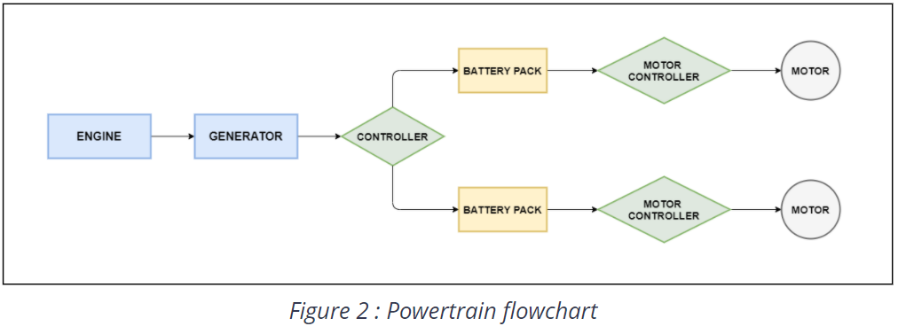
Once the preliminary design was drawn out, an initial power estimation was carried out using total energy equations. Based on which a powertrain configuration was decided and its layout is presented in Figure 2. Following which, momentum theory was used to obtain an initial estimate on the radius of the propellers.
Based on the requirements of the UAV, propellers and wings were designed. The base radius of the propeller is 1.3 m. The propeller was designed with a NACA0012 airfoil with each blade having a linearly varying pitch angle and chord from hub to tip. Several propellers with radii varying in the range of 1.3 0.5 m were analysed to obtain the most efficient design. The airfoil for the wing was chosen to be NACA4412 due to its performance at higher Reynolds number. The dimensions of the wing were decided based on the lift expected from it and the coefficient of lift value obtained from airfoil tools. The total wing area is 60 m2.
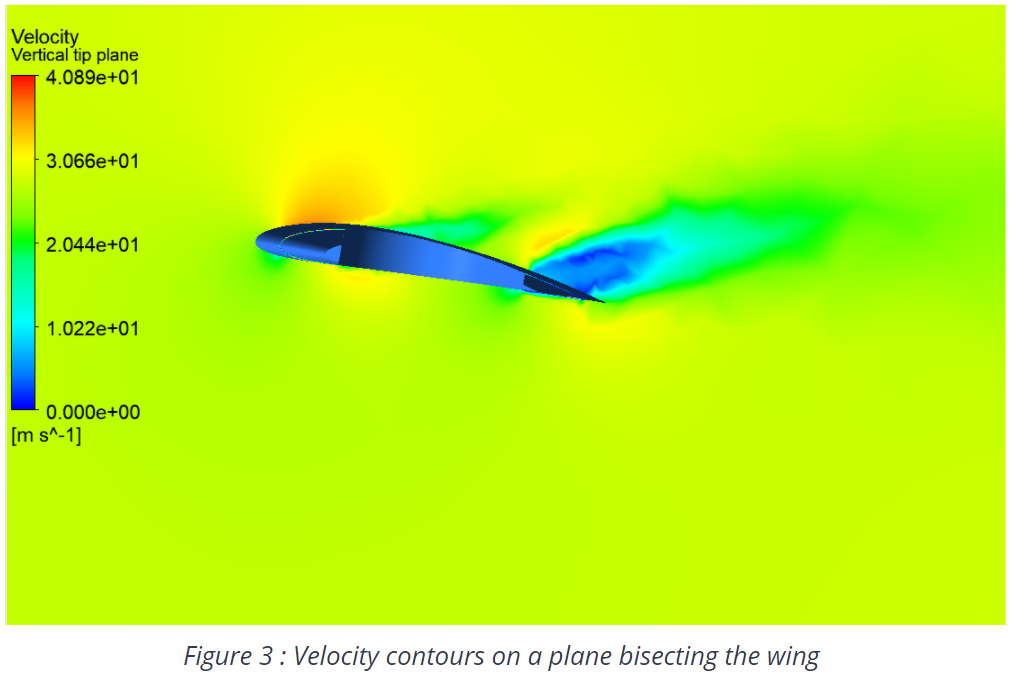
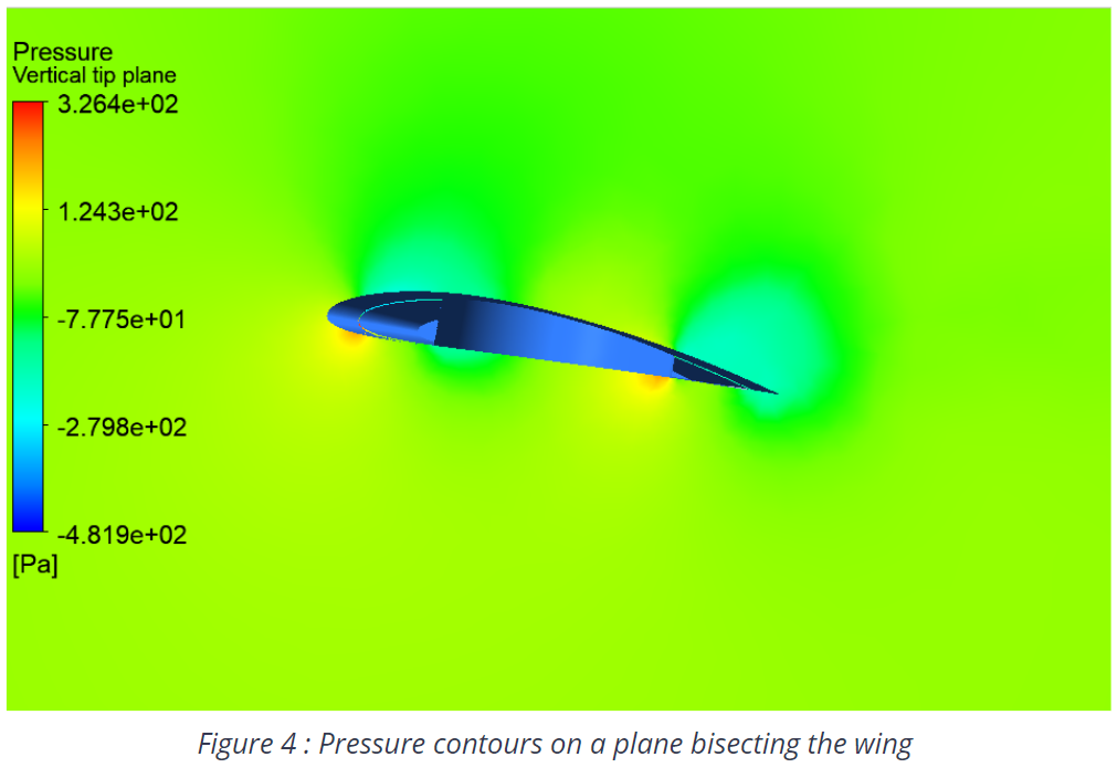
The theoretical propeller performance was obtained from blade element momentum theory (BEM) where the propeller was divided into ten sections and at each of the sections, force and momentum balance equations were applied to get elemental lift, drag, thrust and torque which were summated to get the results for a blade. For the wings, ANSYS simulations were performed using a realizable K-epsilon model with convergence criteria set to less than 0.0001. The operating conditions were the properties of air at 12,000 feet. The inlet condition is the velocity of magnitude 100 kmph. And the outlet is pressure outflow boundary condition.
The cell for our battery pack was selected to be 18650 lithium-ion cells because of their higher power density and longer life as compared to Lithium polymer, lead-acid and other battery types.
Based on the power and torque requirements for the propellers, a suitable motor was selected. We have selected a PMSM because of its high power density, the EMRax 208 was the ideal choice for our scenario. According to the power requirements of the motors, the most efficient battery pack weight was determined to be 200 kg. As we have two motors, two battery packs of 200 kg each is required to ensure the power requirements of individual motors are met. An RR250 engine is selected to satisfy the power requirements.
Once all major components of the aircraft are selected/designed, they are arranged to ensure stability of the UAV. The centre of gravity(CG) of the components is maintained ahead of the mean aerodynamic center(MAC). A fuselage is modeled around it with a slenderness ratio of 5.2 to obtain least drag.
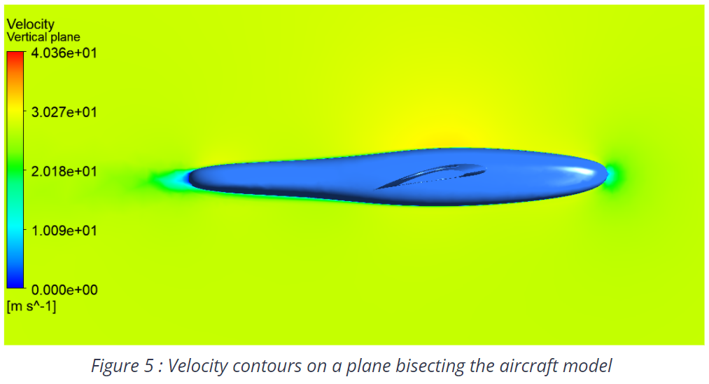
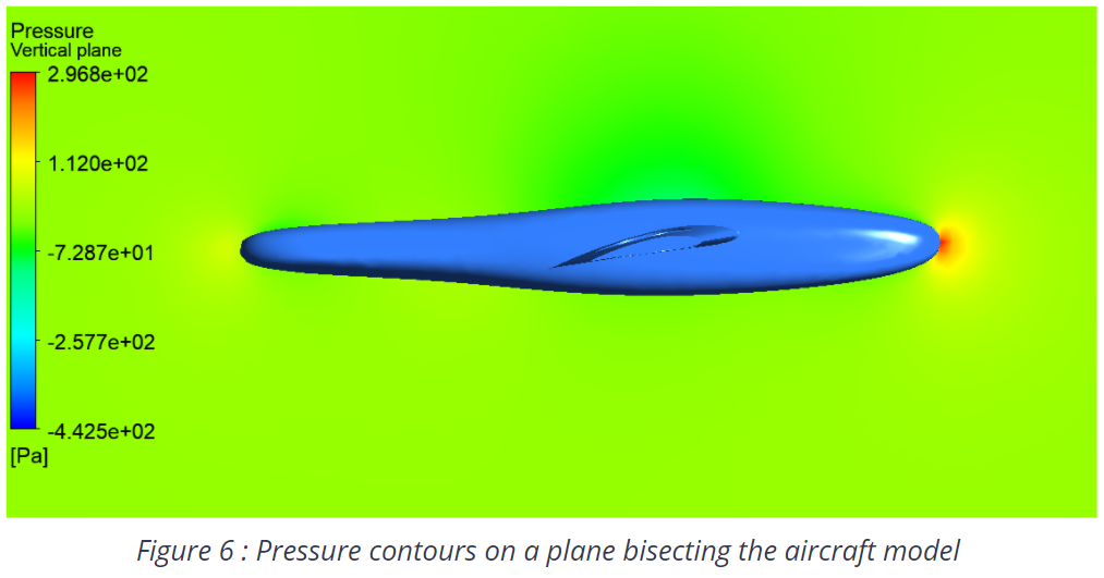
CFD analysis is performed on the entire model using a realizable K-epsilon model with convergence criteria set to less than 0.0001. The operating conditions were the properties of air at 12,000 feet. The inlet condition is the velocity of magnitude 27.778 m/s. And the outlet is pressure outflow boundary condition.
Finally, a complete cost analysis was performed on the aircraft to check its feasibility and profitability.
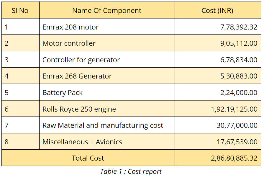
Cost Report
The cost of this concept design is estimated using numbers from aircrafts that have similar power consumptions, maximum take-off weight, wingspan and from manufacturers who provided us with the information. The below table states the estimates. All costs are estimated values and must be treated as such. Depending on prevailing market conditions and environmental factors, these values are subject to change. The cost report does however at all times provide a fair insight into the estimated cost of production of such a UAV. All costs are mentioned in INR and all those parts/components which are to be imported are converted from USD to INR or EUR to INR (a current exchange rate of 72.8 INR to one USD and 86.49 INR to one EUR is taken).
The above mentioned costs can be severely reduced by:
- Mass production
- Setting up our own manufacturing locations
- Contracts with Powertrain suppliers
- Material and component cost optimization
- Custom made engine, fit to mission requirements
Results
After estimating ideal mission energy and performance analysis of our components, the following results were obtained. Both disc actuator and blade element momentum theory for the propellers give us around 730 kg lift during hovering at 2200 RPM, these calculations also ensured that our propeller demanded torque within the motor’s limit. A gear ratio of 1.5 to 2 is to be used depending on the specific requirement.
The CFD analysis of the wing yielded the following results:
- Cl = 0.671
- Cd = 0.092
- Lift = 6698.01 N
- Drag = 926.69 N
The CFD analysis of the entire model aircraft yielded the following results:
- Cl = 0.4121
- Cd = 0.07687
- Lift = 14346.7 N
- Drag = 2676.31 N
The estimated total cost of the aircraft is about 395,639.33 USD which is approximately equal to 28,860,885.32 INR and is well in the range of 250,000 - 300,000 USD which is the cost of most multi-engine aircrafts. At the end, we have a vertical take off and landing aircraft with over 100 kg of maximum payload capacity that can cruise at 100 kmph for more than 200 km as a result of using fixed wings which reduce power consumption drastically.
Aircraft technical specifications:
Conclusions
It is evident from our design numbers that hybrid systems can solve a lot of the current problems and can be advantageous over current all-electric aircrafts in terms of range and speed. Such high altitude applications require the aircrafts to be very flexible in terms of performance and time of flight which the engine can ensure through its constant power generation. Although they are around 3,59,00 dollars which is considerably high as compared to general multi-engine aircraft which cost around 2,00,000 - 2,50,000 dollars.
The current multiple pitchable rotor design gives us an idea into the potential of fixed-wing vertical take off and landing aircrafts which can incorporate the best of both worlds while maximising range, high payload capacity and take off, landing and hovering vertically.
Applications of the UAV –
- Supplies for people affected by natural calamities
- Transport of resources to locations inaccessible by land
- Transport of machinery and important equipment
- Medical transportation
- Military purposes
Target Clients for the UAV –
- Government and other organizations working in rescue and assist
- Private companies in the high cost, high value and quick delivery manufacturing sector
Future Scope
- The power consumption can further be optimised so that the motor is always in its maximum efficiency range through pre-mission planning and path codes.
- Battery pack weight estimations can be done through Simulink after calculation of the power consumption from blade element momentum theory.
- Wing designs can be changed to make it more aerodynamic with the addition of wing tips, back sweep etc.
- Control surfaces can be designed to control the aircraft manually in case of a motor failure
- A new structure for the hollow wing is required along with which the fuselage can be designed.
References
- MIT Electric vehicle team, April 2008, Types of hybrid powertrain
- Politechnico Di Milano, Msc Aeronautical Engineering, Project Report 2017, HybridPowertrainModSim.pdf
- Ya Xie, Savvarisal,Antonios, Dan, Jason; Chinese Journal of Aeronautics Review of hybrid electric powered aircraft with design considerations.pdf
- Journal of Marine Engineering & Technology Analysis of Propulsion Systems of Unmanned Aerial Vehicles
- Dr Paul Roberston, University of Cambridge Hybrid Power in light aircrafts
- Prof Dhwanil Shukla, Department of Aerospace engineering, IIT Bombay Hover performance prediction methods
- Spyridon G. Kontogiannis, John A. Ekaterinaris; Aerospace Science & Technology Design, performance evaluation and optimization of a UAV
- Ahmad Azlan Shah B. Ibrahim, Mohammad Nazri Mohd Jaafar ; Jurnal Mekanikal, December 2008, No 27, 78-90 Power Estimation - Four seater helicopter