Mentors
- Varshini C
- Sumukha S Adiga
Member
- Harish R K
Aim
To study 2-D gas–solid fluidized bed using computational fluid dynamics (CFD) software ANSYS Fluent.
Abstract
The hydrodynamic behavior of a 2-D gas–solid fluidized bed has been studied using computational fluid dynamics (CFD) software ANSYS Fluent. In the present work, the effects of inlet gas velocity, pressure drop and bed expansion ratio was studied. The minimum fluidization velocity condition was predicted by using theoretical formulae. The momentum exchange coefficients were calculated using Syamlal-O’Brien functions. The comparison study showed that the CFD simulation of a gas–solid fluidized bed can be used effectively for the designing and operation of a lab-scale fluidized bed column. The simulation studies would also help in the scaling up of the fluidized bed further for industrial usage.
Introduction
A fluidized bed is a physical phenomenon occurring when a quantity of a solid particulate substance (usually present in a holding vessel) is placed under appropriate conditions to cause a solid/fluid mixture to behave as a fluid. This is usually achieved by the introduction of pressurized fluid through the particulate medium. This results in the medium then having many properties and characteristics of normal fluids, such as the ability to free-flow under gravity, or to be pumped using fluid type technologies. The resulting phenomenon is called fluidization.
Fluidized beds are used for several purposes, such as fluidized bed reactors (types of chemical reactors), solids separation, fluid catalytic cracking, fluidized bed combustion, heat or mass transfer or interface modification, such as applying a coating onto solid items. This technique is also becoming more common in aquaculture for the production of shellfish in integrated multi-trophic aquaculture systems.
The hydrodynamic behavior of a fluidizer gives information on bed material movement along with changes in bed operation. CFD (computational fluid dynamics) is a very promising tool to understand hydrodynamic behavior of fluidized bed reactors. CFD models are mainly categorized into Eulerian-Lagrangian and Eulerian–Eulerian approaches for a gas–solid fluidized bed. Eulerian–Eulerian model is considered as the most appropriate approach in fluidized bed simulation because of faster potential to formulate constitutive equations when compared to EulerianLagrangian method. The coupling of turbulent gas flows and inter-particle collision inside the gas–solid bed of fluidization is a very complex phenomenon which leads to difficulties in designing, scaling up and optimization of gas–solid fluidization.
The efficiency of a fluidized bed quantitatively and qualitatively depends on the particle diameter, density, cross sectional area of bed. These may lead to bubbling and slugging in the beds which needs to be avoided. Pressure drop and bed expansion ratio and minimum fluidization velocity both depend on the particle characteristics. The present work aims to carry out two phase CFD simulation of the fluidized bed and validation of the hydrodynamic behavior of biomass fine particles in fluidized bed column with experimental data observations. In the CFD simulation, the Eulerian–Eulerian model approach along with the theory of granular flow for the 0.0003 m sized biomass particles has been used. The simulation is carried out at different inlet gas velocities computationally and the hydrodynamics of bubbling gas–solid fluidized bed has been studied and compared with the experiment.
Modelling
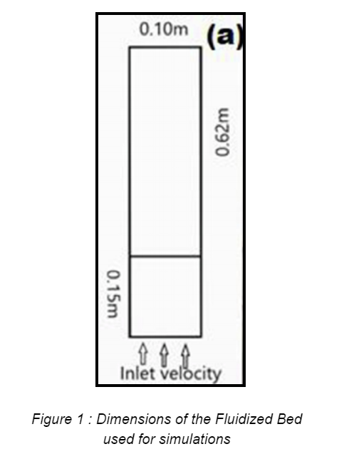
The 2D gas-solid Fluidized bed was modelled using Ansys Fluent (Student version,2020 R2). Dimensions of the Fluidized Bed :
- The bed width was taken to be 0.10m.
- The bed height was taken as 0.62m.
- The initial solids packing was taken to be 0.15m.
Figure 1 shows the dimensions of the bed.
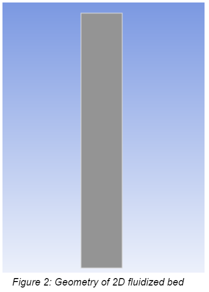
Geometry
The 2D fluidized bed was designed using Ansys Design-Modeller. The sketching plane was chosen to be the XY plane. A rectangle was drawn on the XY plane. The rectangular sketch was made using the ‘surface from sketches’.
Meshing
The element size for the mesh was taken as 0.002m. Linear elements were chosen to generate the mesh. The element size for the mesh was chosen by assessing the mesh quality at different element sizes.
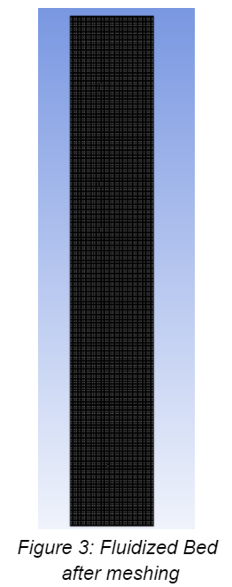
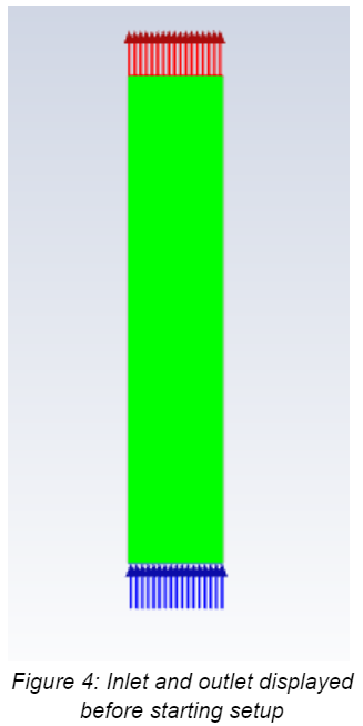
The named selections used for the mesh (Figure 3) are :
- Inlet: The lowermost part of the bed is taken to be inlet. This is where the gas (air) enters from.
- Outlet: The upper part of the bed is taken to be the outlet. The gas exits from here.
- Walls: The lateral sides of the bed are the walls.
- Fluid: The body of the Bed is taken as the fluid domain.
Setup
Eulerian Multiphase model was used to model the 2D Fluidized bed. Fluid inflow was modelled using the Viscous laminar model. A new fluid named solid with a density of1242 kg/m3 was created. The diameter of the solid was fixed at 0.0003 m. Syamlal and O’Brien drag model was chosen to model the granular viscosity and the drag coefficient.
Boundary conditions :
- Inlet velocity (gas): 0.05m/s,0.10m/s,0.15m/s,0.19m/s,0.55m/s
- Outlet gauge pressure (mixture): 0 Pascal
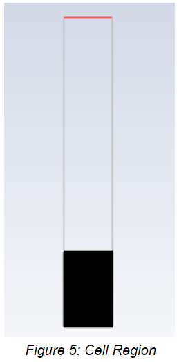
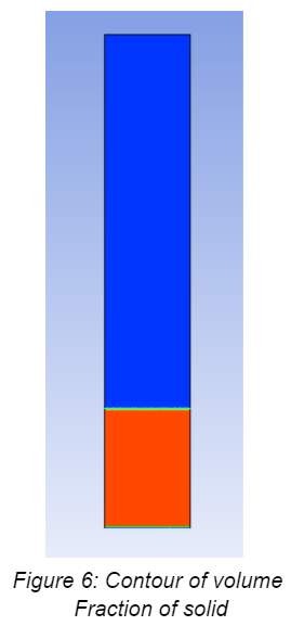
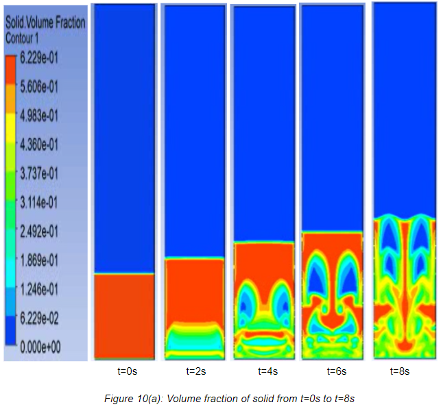
In solution methods, the transient formulation was changed to Second Order implicit. A new cell region was added by specifying the coordinates of the region. The cell region was patched with a volume fraction (solid) of 0.6. The contour of the volume fraction (solid) was added. A solution animation was added for the contour. The number of time steps was chosen to be 1500 and the time step size was chosen to be 0.001s. The results were calculated after the solution initialization.
Results
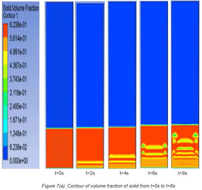
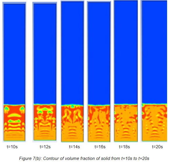
Simulations
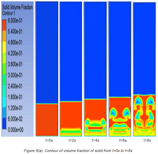
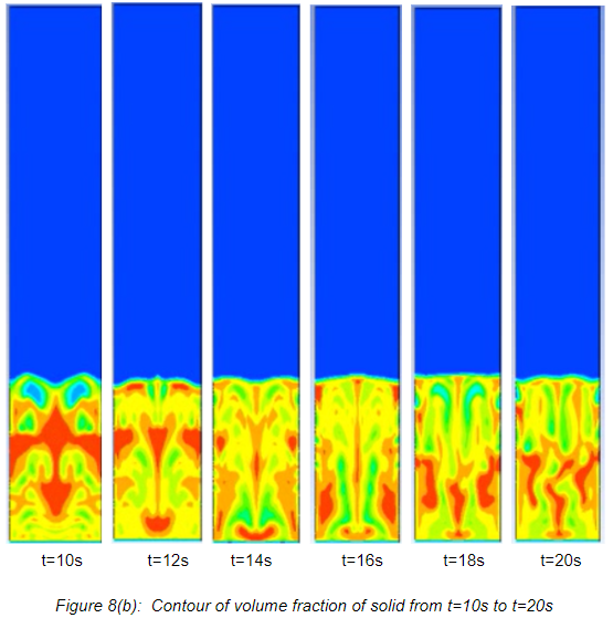
- Contours of Volume Fraction at inlet velocity 0.05 m/s.
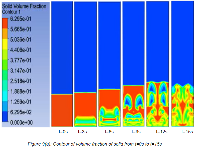
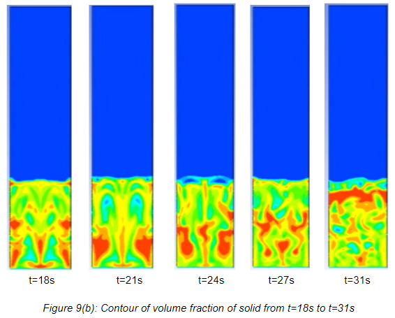
- Contours of Volume Fraction at inlet velocity 0.10 m/s.
- Contours of Volume Fraction at inlet velocity 0.15 m/s.
- Contours of Volume Fraction at inlet velocity 0.19 m/s.
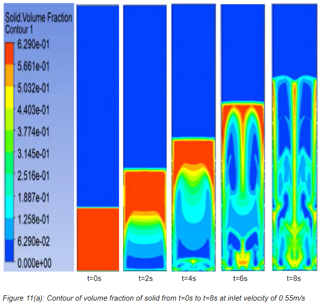
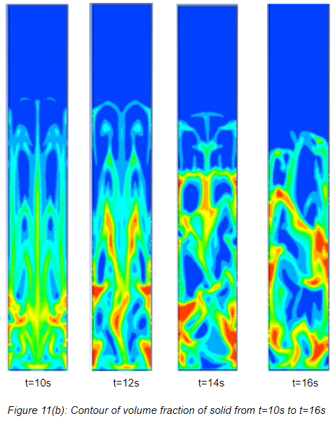
- Contours of Volume Fraction at inlet velocity 0.55 m/s.
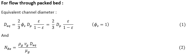
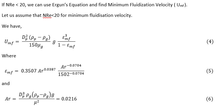
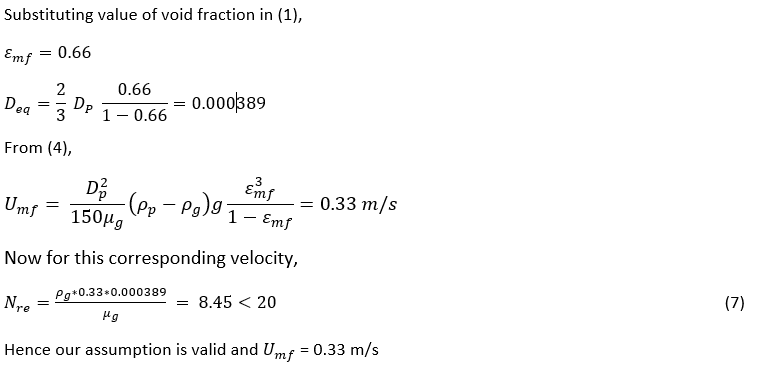
Calculations
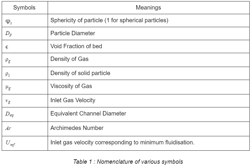
Nomenclature
Conclusion
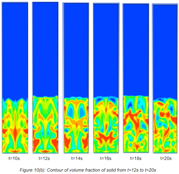
- The gas–solid fluidized bed was simulated at different inlet velocities, the result showed the bed height increases with increase in velocity. It can be observed that inlet gas velocity has a very big impact in fluidization phenomena. Pressure drop, bed expansion ratio and formation of bubbles are directly related to the inlet velocity. All the case studies showed that at velocities of 0.15 m/s to 0.55 m/s the bed height increased with increase in velocity. At higher velocities the gas volume fraction is larger and leads to higher bed expansion.
- After the initial increase in bed height along with the gas velocity, the bed height remains almost constant.
- From calculations using Ergun’s Equation, the Minimum Fluidization Velocity is 0.33m/s.
- At higher velocity the biomass inside the bed moved towards the top of the bed and turbulent and lean fluidization occurred. The velocity above 0.55 m/s may result in the elutriation of the bed.
References
- CFD modeling of a typical fluidized bed column
- CFD Modeling of Fluidized Bed Systems
- Siemens Report
- Minimum fluidization velocity, bubble behaviour and pressure drop in fluidized beds with a range of particle sizes
- CFD modeling to determine the minimum fluidization velocity of particles in gas-solid fluidized bed at different temperatures
- Fluidized Beds
- Unit Operations in Chemical Engineering by McCabe W.L., Smith J.C., Harriott P