Mentors
- Kaustubh
- Ajethesh
Members
- Akash Deepak Shah
- Samith Hegde
Abstract
Aerofoil is the cross-sectional shape of an object that creates an aerodynamic force when moved through a fluid. Aerofoils are used in aircrafts either as wings to produce or as propeller blades to produce thrust. Drag Reduction System (DRS) is an innovative system introduced by FIA (Fédération Internationale de l’Automobile) in 2011 to enable overtaking of a car closely behind another. This system lets drivers to open a flap in the rear wing at certain parts of the race track. This flap opening removes much of the drag produced by the rear wing, adding around 15 kmph more to the car’s top speed, thus enabling easy overtaking along straights. DRS is activated by the driver, and can be deactivated either manually or automatically when the brakes are applied.
Objective
- To determine the feasibility of implementing a drag reduction system on a rear wing, by analysing the model using CFD.
- To find the optimum angle of attack on the rear wing that minimizes drag and minimizes the loss of downforce on the rear wing.
Literature Survey
After doing the literature survey, several aerofoils were chosen for analysis : NACA 6412, Selig 1223, GOE 448 and GOE 464.
CFD Analysis using Ansys
Analysis was done on multiple aerofoils mentioned above for the optimum lift to drag ratio and Selig 1223 and GOE 448 were chosen for the DRS.
The CFD analysis of DRS was conducted using Ansys Fluent. The analysis can be split into four parts : Geometry, Meshing, Setup & Solution, and Results.
Geometry
For individual aerofoil analysis
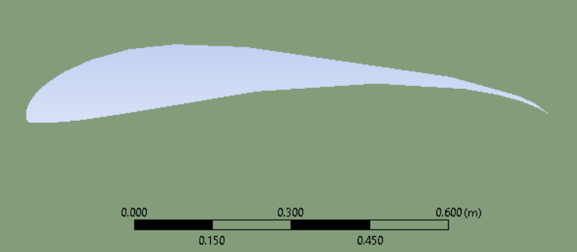
The aerofoils were created by importing the coordinates from a txt file in Design Modeller. A bullet shaped fluid domain region was constructed. The aerofoil surface was subtracted from this region using the Boolean operation.
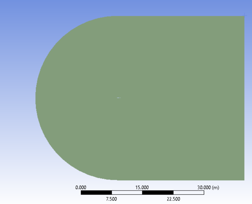
Selig 1223 Geometry:
For DRS analysis
Constraint: The aerofoils must be within a 350mm by 220mm box according to FIA standards
The aerofoils were created by importing the coordinates from a .txt file in Design Modeller and manipulated to get the correct shape (scaled, rotated, and then translated). A large rectangular fluid domain region was constructed around the aerofoil. The aerofoil surfaces were subtracted from this region using the Boolean operation.

Meshing
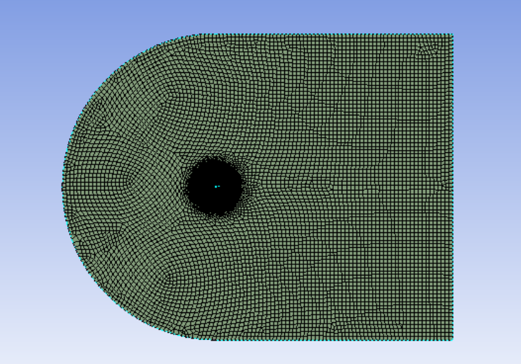
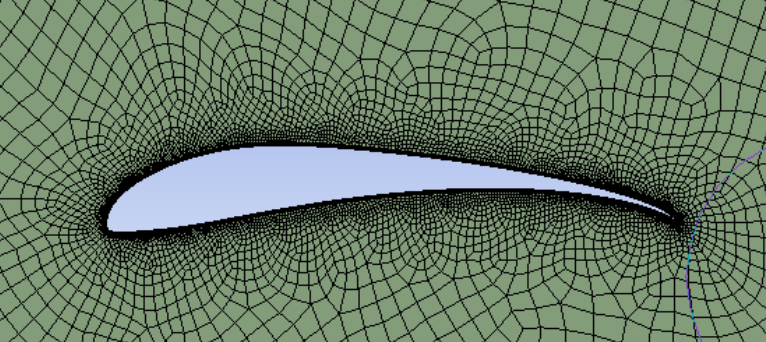
For individual aerofoil analysis
The mesh used is inflation-type mesh with a body sizing around the aerofoil and edge sizing to get finer elements. Finally, a grid independent study was conducted with a tolerance limit of 1%.
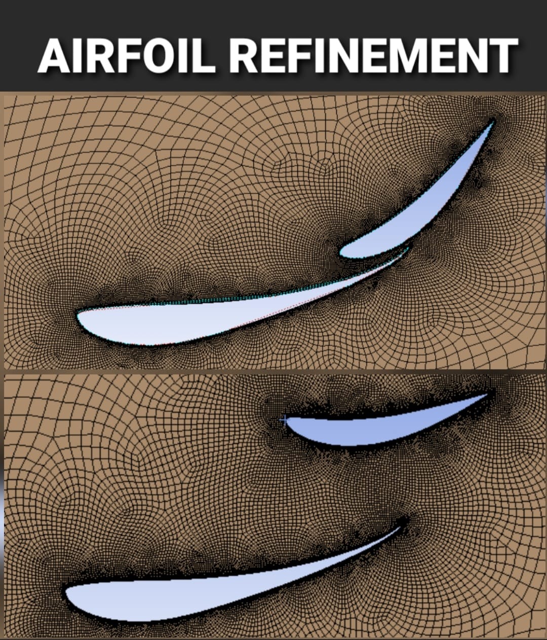
For DRS analysis
The mesh used is of refinement type. Every edge of the aerofoil has edge sizing and a grid independent study was conducted with a tolerance limit of 1%.

Setup & Solution
Turbulence Model used for Analysis : Spallart-Allmaras (one-equation model)
Method : Coupled (Pseudo-Transient)
Setup Parameters:
- Reynold’s Number = 3e+6
- Fluid : Air
- Fluid Density = 1.225 Kg/(m^3)
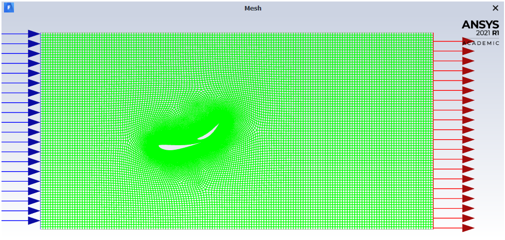
- Boundary Conditions :
- Left Boundary : Velocity Inlet
- Right Boundary : Pressure Outlet
- Upper and lower boundary - Zero Shear walls
- Aerofoil edge - No Slip walls
 Setup of the closed DRS model for Angle of Attack = 8 degrees on the main wing)
Velocity Inlet : 3 values of inlet velocity were chosen (30 m/s, 43.33 m/s and 50 m/s) and analysis of all three was conducted with the selected angles of attack 12 degrees and 8 degrees on the main wing.
The Angles of Attack were chosen based on the literature survey conducted. The selected Angles of Attack produce the best results (minimum drag and maximum downforce) on Selig 1223 individually.
The angle of attack on the open system was 8 degrees in both the analyses, chosen based on the literature survey.
Results
The results obtained from the analysis are as follows:
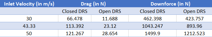 Angle of Attack on main wing (Selig 1223) = 12 degrees
Approximate reduction in Drag = 75%
Approximate reduction in Downforce = 20%
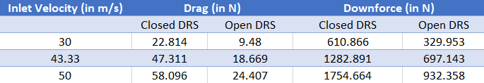 Angle of Attack on main wing (Selig 1223) = 8 degrees
Approximate reduction in Drag = 57%
Approximate reduction in Downforce = 47%
From the above tables, it can be concluded that the optimum angle of attack is 12 degrees on the main wing for maximum reduction in drag and minimum loss of downforce.
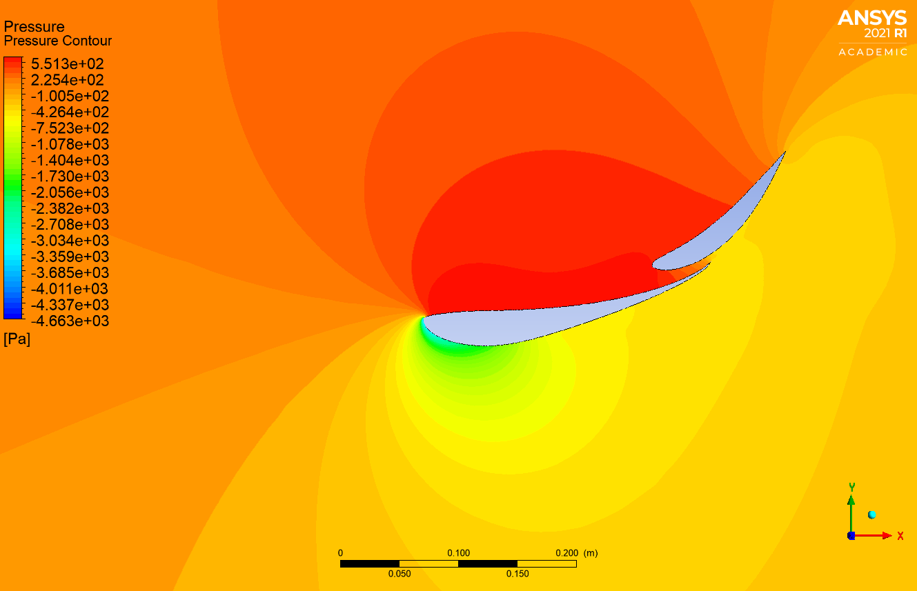
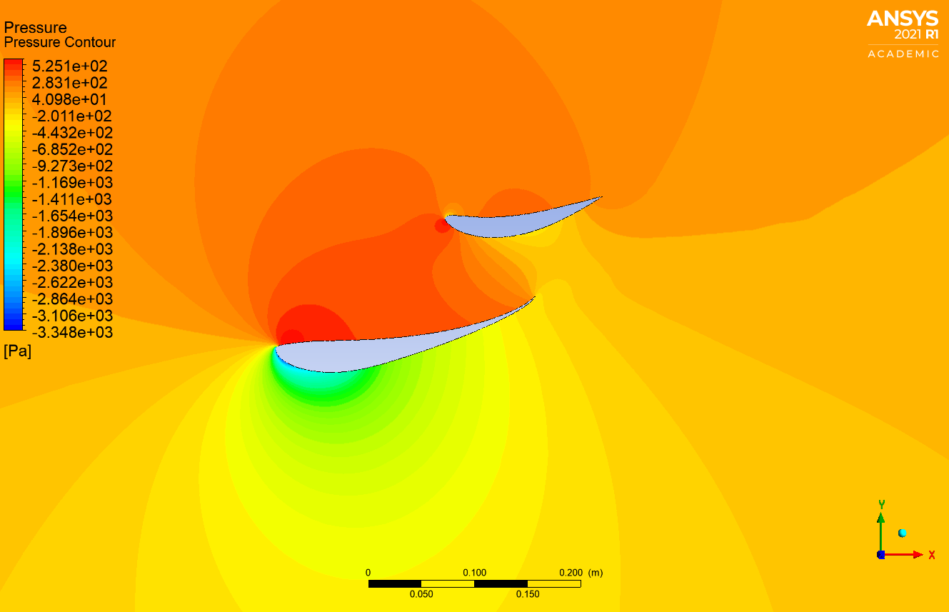 Comparison of Pressure Contours over the rear wing in Closed DRS (top) with Open DRS (bottom) for AoA = 12 degrees and u = 30 m/s
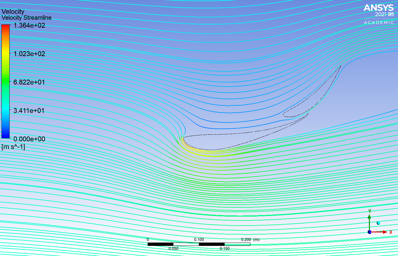
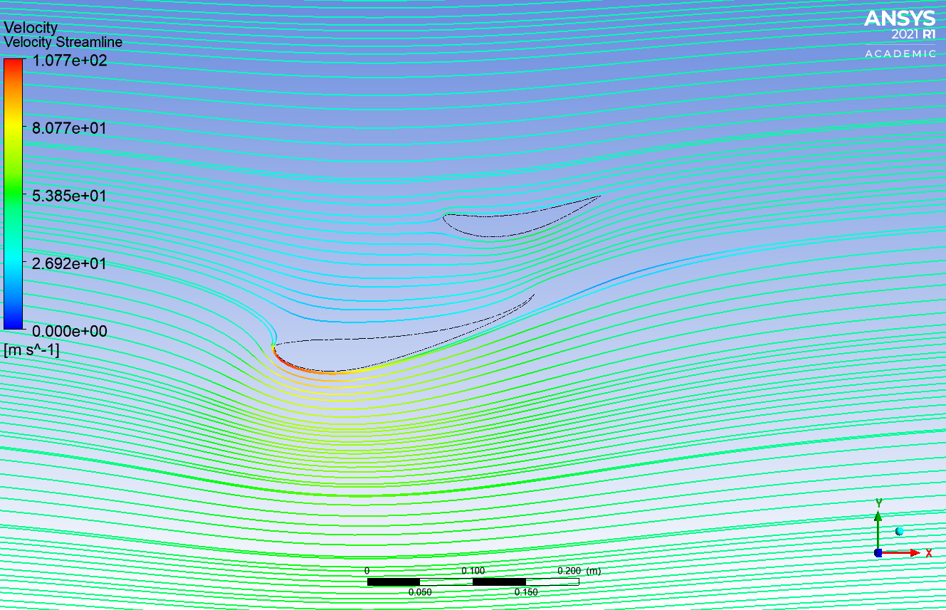 Comparison of Velocity Streamlines over the rear wing in Closed DRS (top) with Open DRS (bottom)) for AoA = 12 degrees and u = 43.33 m/s
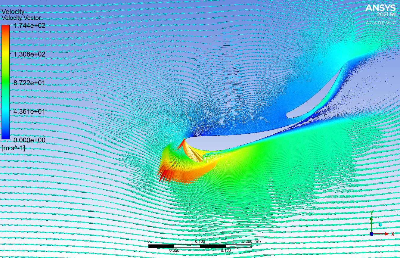
 Comparison of Velocity Vectors over the rear wing in Closed DRS (top) with Open DRS (bottom) for AoA = 12 degrees and u = 50 m/s
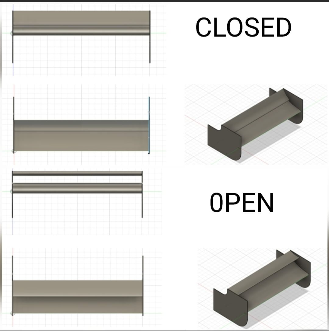
3D Model
The 3D model was constructed on Fusion and can be used to conduct further analysis on the rear wing so as to optimize it along with the end plates.
Conclusion
From the tables and graphs, it can be observed that a Drag Reduction System can be successfully implemented on the rear wing of an F1 car to increase speed and enable overtaking, since it would result in a substantial decrease in the drag force on the rear wing, although the downforce on wing would be decreased as well.
It can also be seen from the literature survey and the analysis conducted that :
- Selig 1223 is to be chosen as the main wing and GOE 448 as the flap for optimum results.
- The angle of attack on the main wing should be 12 degrees and on the flap, in the open DRS configuration, should be 8 degrees.
References
- Development of a Drag Reduction System (DRS) For Multi-Element Race Car Wings S. Wordley, D. McArthur, L. Phersson, D. Tudball Smith and D. Burton. Department of Mechanical and Aerospace Engineering, Monash University Clayton, VIC 3800, Australia
- The F1 Drag Reduction System (DRS)
- F1’s Tyre Rules (2016) Explained
- Study on airflow characteristics of rear wing of F1 car. A R S Azmi et al 2017 IOP Conf. Ser.: Mater. Sci. Eng. 243 012030
- Development and Implementation of Multi Element Aerodynamic Devices with Drag Reduction System for a Formula Student Vehicle