Mentors
- M N Vishnu
- Shubham Swadi
Members
- Dhruv M N
- Mallikarjun
- Megha Rajagopal
- Syed Abubaker Bin Junaid
Acknowledgements
We would like to thank IEEE NITK Student Branch for conducting Envision 2023
Aim
The aim of this project includes getting familiar with concepts related to digital electronics like sequential circuits, learning how to code in hardware description languages like Verilog and use of softwares like Vivado.
Introduction
We live in a world surrounded by all sorts of digital equipments. Inspired by all this digitalization, we decided to implement a digital lottery system based on the concepts of digital electronics. The lottery system would use an internal logic to select a winner at random. The digital components used for the lottery system are registers, linear feedback shift register, counter and a clock pulse.
Implementation
Inputs
- Lucky bit
- Write bit
- Stop bit
- Clock pulse
Outputs
- Winner Display
- Counter Display
Logic
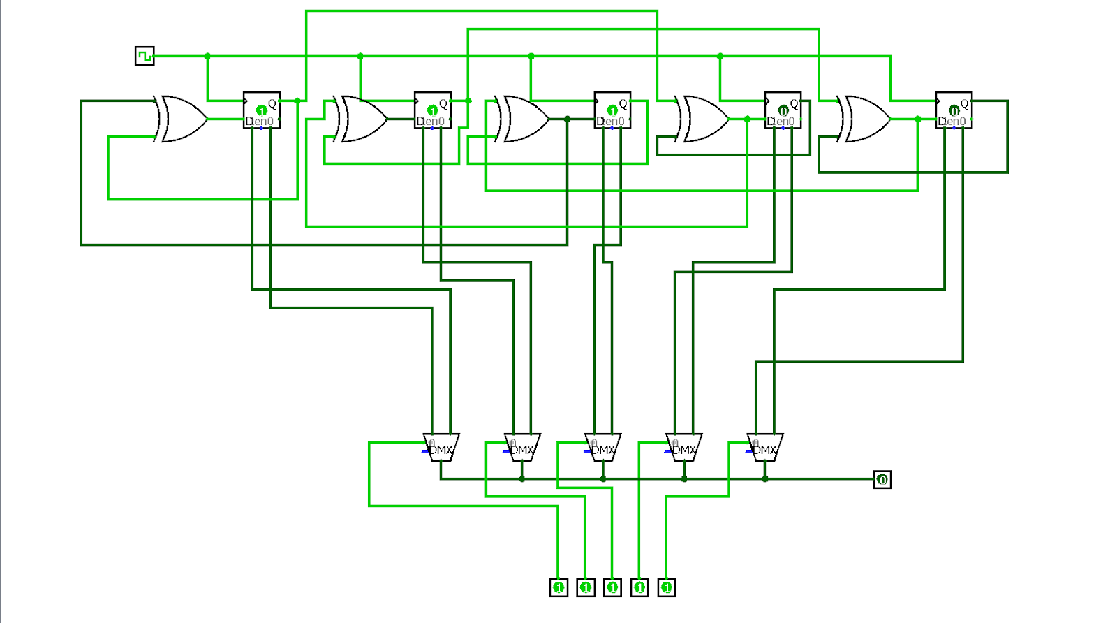
The Digital Lottery System is a system that allows participants to enter a lottery by entering a random bit. The system has a maximum capacity of 32 participants, and each participant is assigned a participant ID. The lucky bits of the participants are stored in a lucky queue in order of participant ID. The winner of the lottery is determined by generating a 5-bit number from the lucky queue using a linear feedback shift register (LFSR). The LFSR is initialized with a random number of bits from the lucky queue, and then it is updated at each clock cycle, generating a random number. When the stop bit is asserted or the maximum number of participants are reached, the LFSR stops updating the value and the final value of the LFSR is taken as the winner.
Here are the steps involved in the Digital Lottery System:
- Each participant enters a random bit.
- The system assigns the participant a participant ID.
- The participant’s lucky bit is stored in the lucky queue in order of participant ID.
- A 5-bit number is generated from the lucky queue using an LFSR.
- The winner of the lottery is the participant with the ID corresponding to the generated 5-bit number.
- The Digital Lottery System is a fair and random way to select a winner from a group of participants. The system is easy to use and can be used to conduct lotteries of any size.
Here are some additional details about the Digital Lottery System:
- The lucky bit can be generated by any random process, such as flipping a coin, rolling a die, or drawing a card.
- The LFSR is a type of digital circuit that can be used to generate random numbers.
- The stop bit is used to signal the end of the lottery.
- The counter display shows the current number of participants in the lottery.
- The winner display shows the ID of the winner.
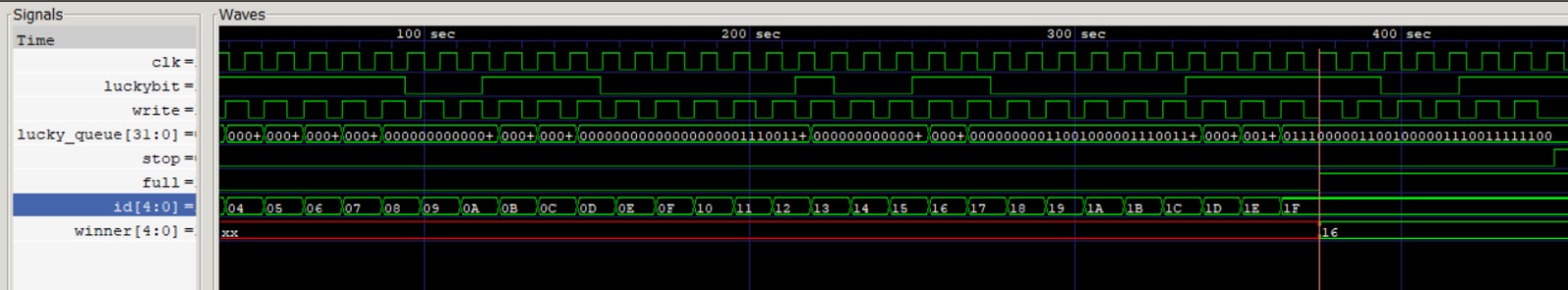
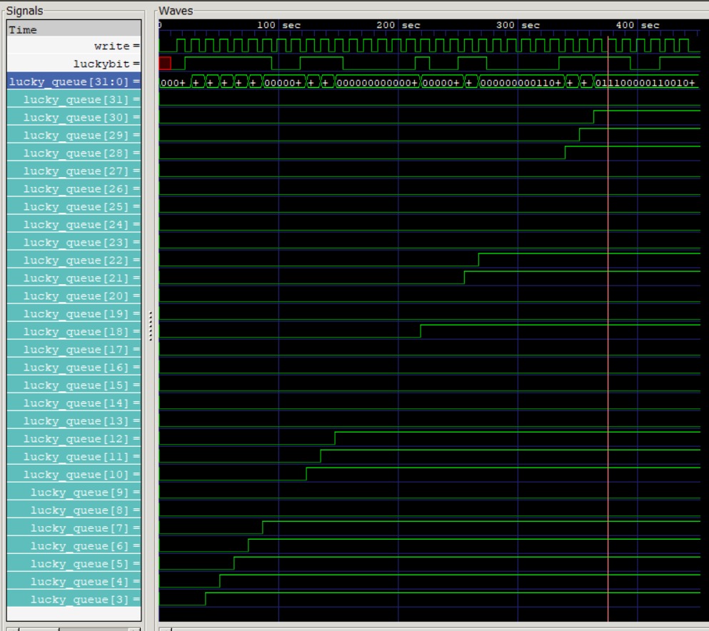
Simulation & Results
The testbench is an important part of the development process for any Digital System. It helps to ensure that the system is working correctly before it is used in a real-world application. This testbench is a piece of software that is used to test the Digital Lottery System. The testbench generates random luckybits, clock, write pulse and stop signal, and then checks the output of the system to make sure that it is correct by using simulation interface called GTKWave. The testbench is written in a modular fashion, so that it can be easily reused for other projects. The testbench also includes a number of features that make it easy to use, such as a graphical user interface and a built-in simulator such as GTKWave.
Here are some of the benefits of using a testbench:
- It can help to identify bugs in the system early in the development process.
- It can help to improve the quality of the system.
- It can help to save time and money in the long run.
Future Scope
We can try implementing the existing logic on FPGA boards such as Basys Artix-7.
Conclusion
- A digital lottery system was successfully simulated on verilog.
- Key concepts of digital electronics and hardware description languages were learnt in the process.
- This project serves as an introdcution to future projects on design of digital systems.