Designing Spur Gear and Analyzing gears for material selection
Mentors
- Ashish Vinay Pastay
- Bhuvan A P
- Chirag Agarwal
Members
- U Manjubashini
- Ashlesh K
- Dharmesh Raikwar
- Kovidh Singh
Aim
To design Spur Gear and compare the simulation results for Spur Gear, Helical Gear and Bevel Gear for four different materials, namely Cast Iron, Bronze, Brass and Aluminium Alloy. The objective is to evaluate and determine the best material for these three different gears based on Total deformation, Equivalent Stress, Maximum Principal Stress, Stress Intensity and Safety Factor.
Introduction
Gears are cylindrical wheels with toothed projections on their peripheral circumference. They are used for power transmission by meshing the teeth of one gear with the teeth of another gear. Unlike belt drives, gears overcome the limitation of slippage that occurs at higher speeds and torque requirements. Gears provide a more reliable and efficient method of transmitting power by maintaining a positive and constant engagement between the gear teeth, ensuring accurate and consistent power transfer. Gears are of different type according to the type of application -
-
Spur Gear - It is a type of cylindrical gear with straight teeth that are parallel to the gear axis. It is one of the most common and simplest types of gears used in case of power transmission between parallel shafts.
-
Helical Gear - It is a type of gear with helically-cut teeth that are oriented at an angle to the gear axis. The teeth on a helical gear are not parallel to the axis of rotation but instead form a helix pattern around the gear. This helix angle allows for a smooth and gradual engagement between the gear teeth, resulting in quieter operation and increased load-carrying capacity compared to spur gears. Helical gears are used for parallel or non-parallel shafts.
-
Bevel Gear - It is a type of gear that has cone-shaped teeth and is used to transmit power between non-parallel intersecting shafts. The teeth of a bevel gear are cut on the surface of a cone, allowing the gear to mesh with another bevel gear at an angle. This design enables the transmission of rotational motion and torque between shafts that are oriented at different angles.
In this project, a Static-Structural analysis will be conducted on these gears under meshing conditions with similar operating conditions and loads to evaluate their mechanical behavior. The primary objectives are to determine the Total Deformation, Equivalent Stress, Maximum Principal Stress, Safety Factor and Stress Intensity developed in the gears for four different materials: Cast Iron (Ductile), Bronze (C51000), Brass (C37700), and Aluminium Alloy (Wrought,6061, T6). Based on the analysis findings, the goal is to recommend the most suitable material for the gear application by assessing and comparing the mechanical performance of the gears made from these different materials. The findings of this study can help gear manufacturers and designers in selecting the most suitable material for a particular gear application, which can improve the efficiency, reliability, and lifespan of the gears.
Geometry
Spur Gear
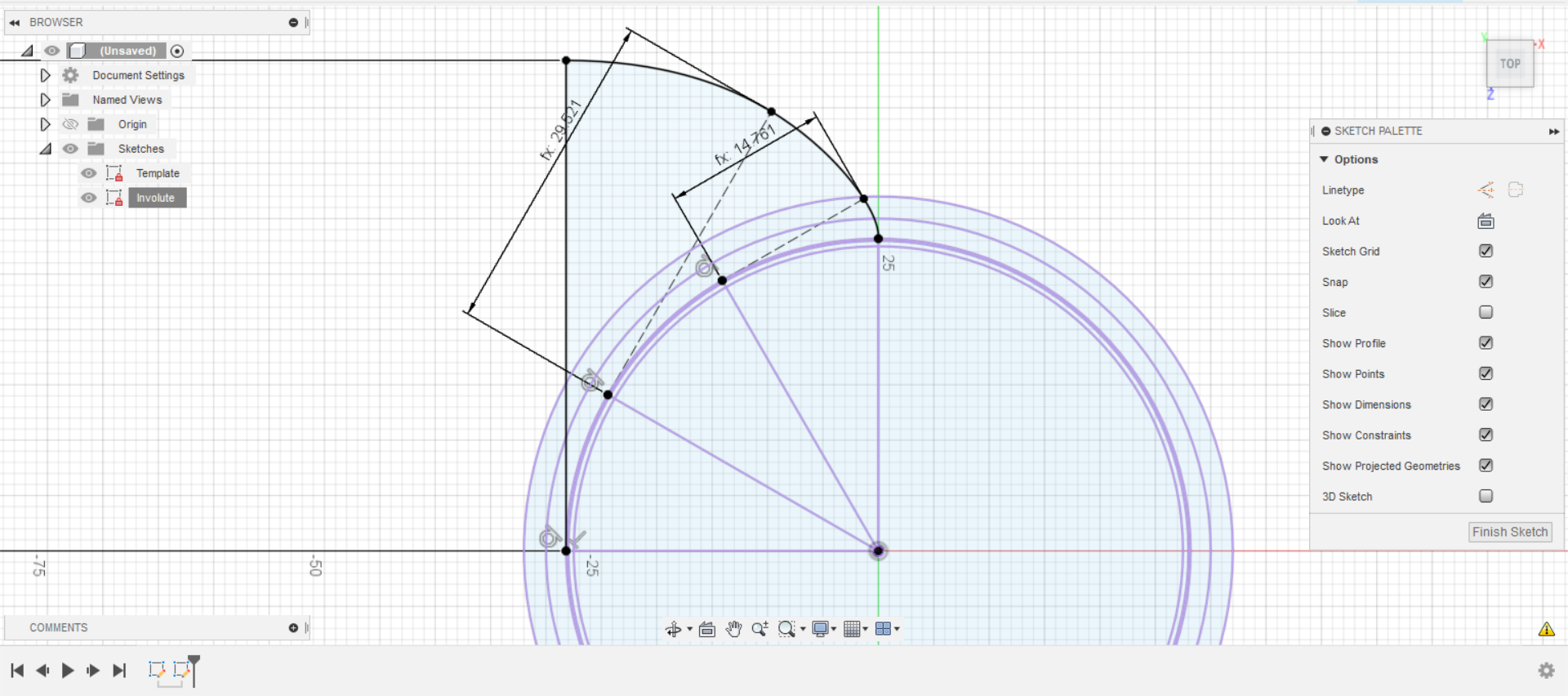
Spur gear is designed with an involute profile. The profile is formed by unwrapping a string from the base circle of gear, resulting in a curved shape known as involute curve. The flank of the gear tooth is always tangent to base circle at any point along length which ensures smooth power transmission.
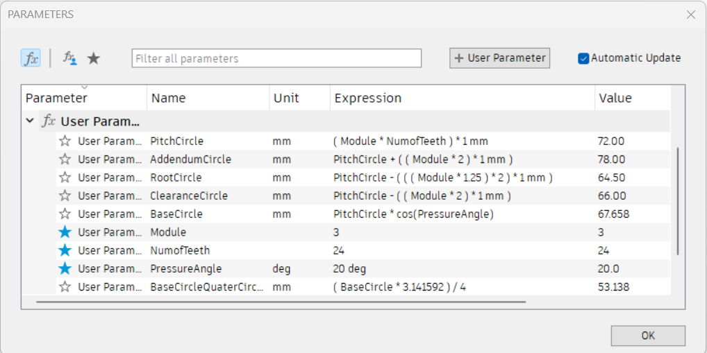
Spur gear is designed in fusion 360 using Module, Number of Teeth and Pressure Angle as Input. Later,required dimensions are defined in terms of Input.
User Parameters
Involute Profile
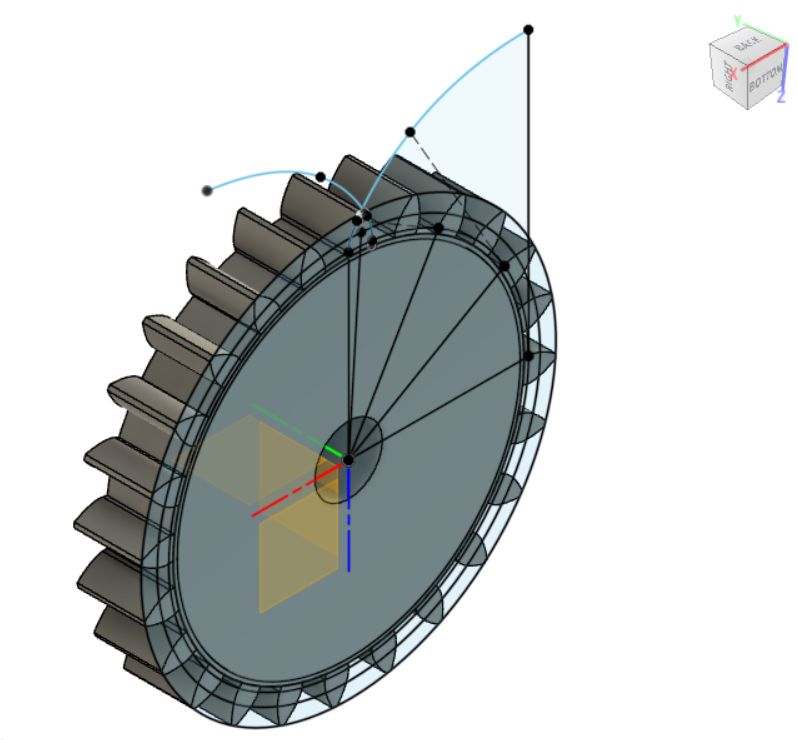
Final Geometry
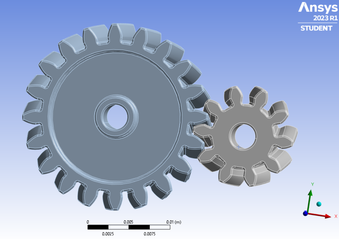
Similarly, Pinion gear is obtained by changing the Number of Teeths to 12. Then Gear and Pinion are meshed together. Gear ratio = 2 , Distance between center of gears = 54 mm.
Helical Gear
Assembled Model of Helical Gear is imported directly from GrabCad to Ansys. Number of teeth in Gear(Driven gear) = 20, Gear Ratio = 2, Helix Angle = 16°.
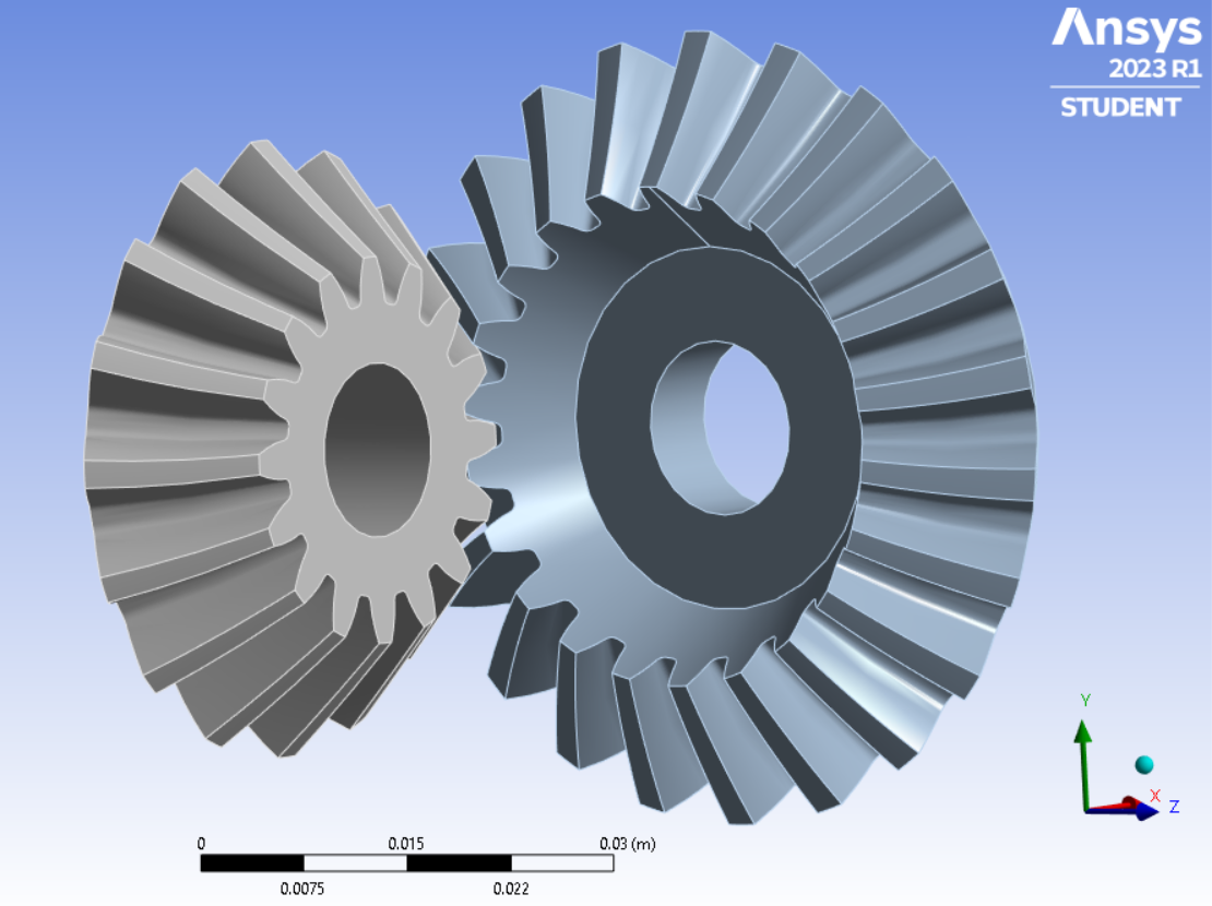
Bevel Gear
Assembled Model of Bevel Gear is imported directly from GrabCad to Ansys. Number of teeth in Gear(Driven Gear) = 22, Gear Ratio = 1.37, Gear Pitch Cone = 82.2°, Pinion Pitch Cone = 115.2°, Angle between Axis = 90°.
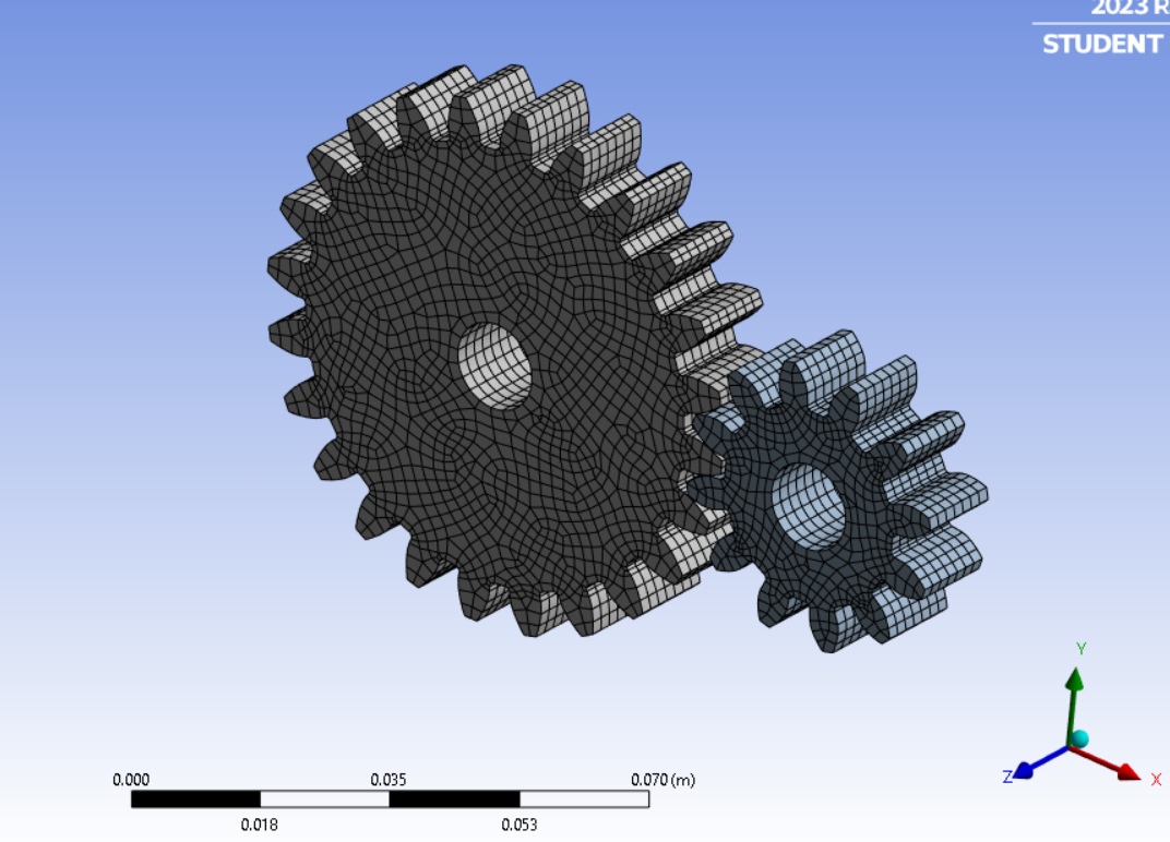
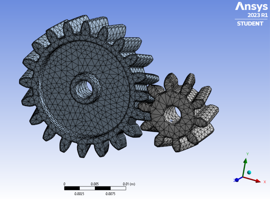
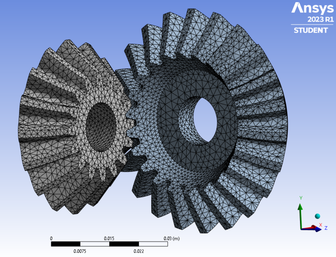
Meshing
The models were meshed with an element size of 1 mm and all the parameters are left as default.
Theory
Total Deformation
Total deformation refers to the overall change in shape or displacement experienced by a structure or component under applied loads. It is a measure of how much the object has deformed or moved from its original position due to external forces or loading conditions. Total deformation considers both elastic and plastic deformation, including bending, stretching, twisting, and any other changes in shape that occur as a result of the applied loads.
Equivalent Stress (Von Mises)
It is used when there is a multiaxial stress state with multiple stress components acting at the same time in the structure. In such cases, we can use the selected criterion to transform the whole stress tensor into a single equivalent component that can be treated as tensile stress and thus compared with material’s strength easily.
Maximum Principal Stress
Maximum Principal Stress is the highest value of normal stress acting on a material in a specific direction, known as the principal direction.
Stress Intensity
Stress intensity is a measure of the magnitude of stress concentration or stress amplification at the tip of a crack or flaw in a material. It quantifies the potential for crack propagation and fracture in the presence of applied stress.
Safety Factor
Safety Factor refers to a numerical value that represents the ratio of the material’s strength or load-carrying capacity to the applied load or stress. A higher safety factor indicates a greater level of safety, as it signifies a larger margin between the applied load and the material’s capacity to handle that load.
Setup
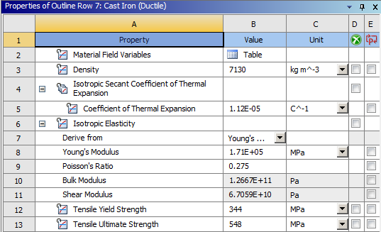
- Cast Iron (Ductile) material was added in Engineering Data with the following properties.
-
Bronze(C51000), Brass(C37700) and Aluminium Alloy, wrought, 6061, T6 materials were chosen from ANSYS GRANTA Materials Data.
-
Fixed Support was defined for the bore face of the Gear.
-
Frictionless Support was defined for the bore face of the Pinion.
-
Moment of 50 N-m was applied to the bore face of Pinion and was defined by Component.
Results
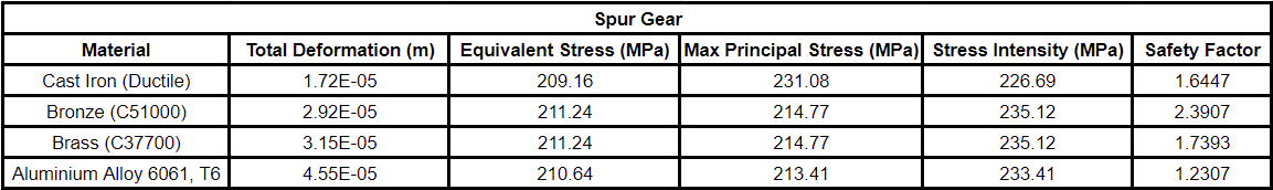
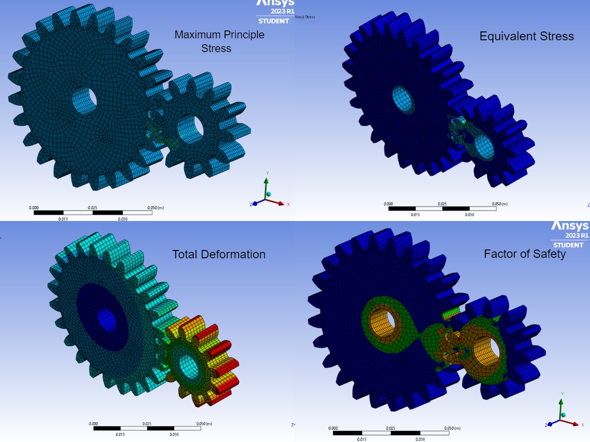
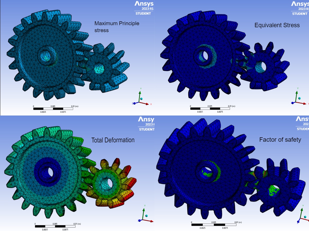
Spur Gear
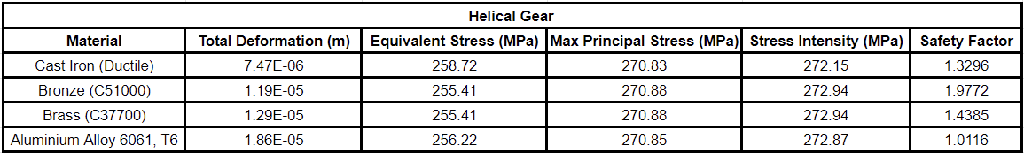
Helical Gear
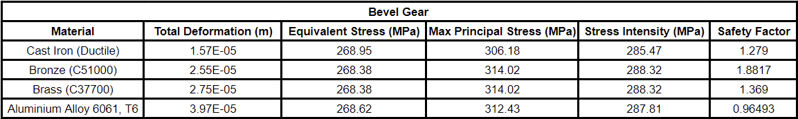
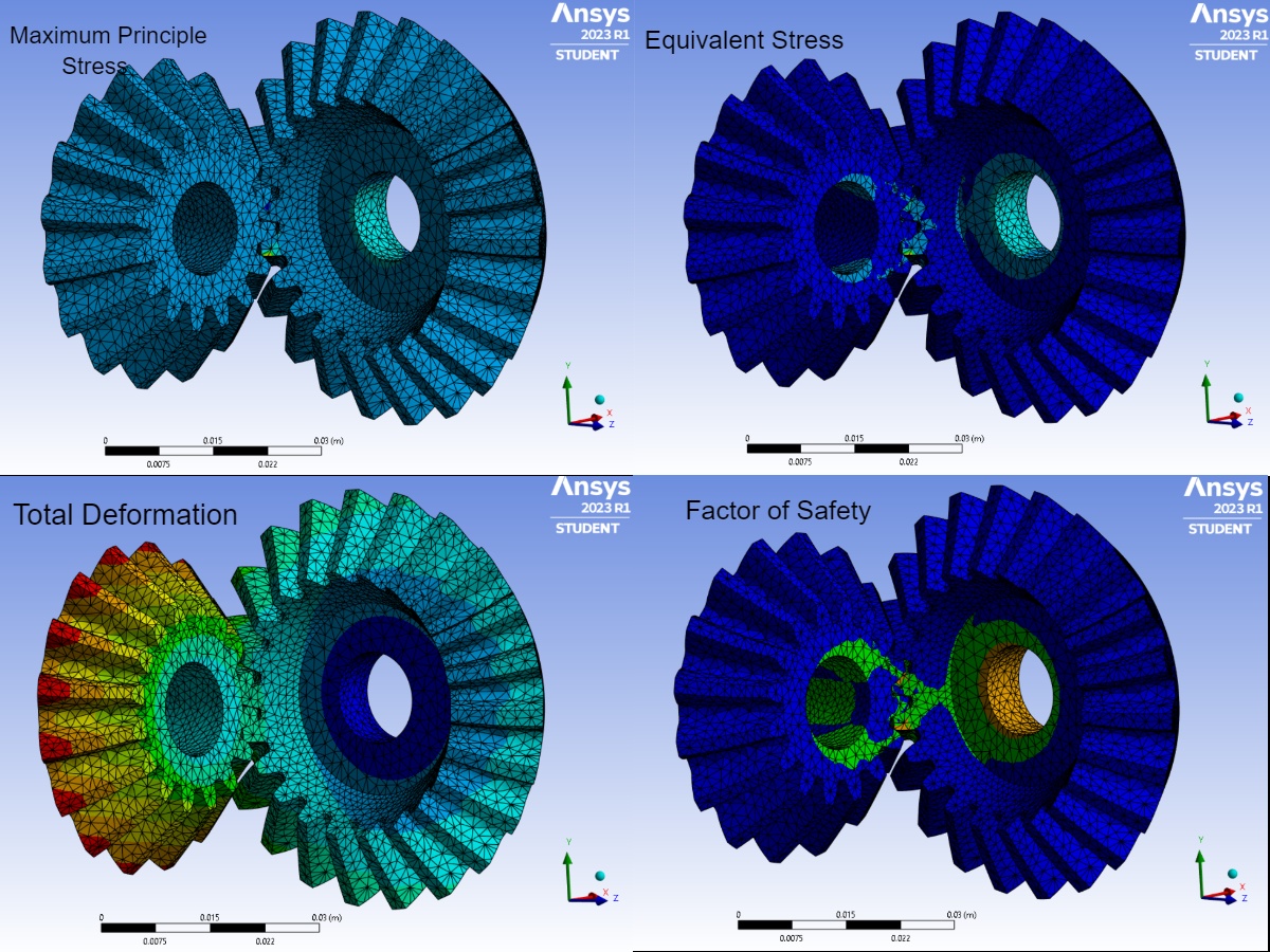
Bevel Gear
Conclusion
-
Considering the results, Bronze (C51000) demonstrates a higher safety factor for all three gears compared to the other materials, indicating a greater margin of safety and reliability.
-
It also exhibits a relatively lower total deformation and stress intensity, suggesting improved mechanical performance and reduced risk of fracture. It is also known for its high wear resistance, low coefficient of friction, and good machinability, making it a suitable material choice for gears that require durability and reliable power transmission.
-
Although Cast Iron (Ductile) has a slightly lower safety factor compared to Bronze (C51000), it still demonstrates acceptable mechanical performance and a reasonable margin of safety. Cast Iron is known for its high strength, excellent wear resistance, and good damping properties, making it a reliable material choice for gear applications.
-
Additionally, Cast Iron offers advantages such as cost-effectiveness, ease of manufacturing, and widespread availability.
-
Brass (C37700) has a similar safety factor as Cast Iron (Ductile) for all three gears, it exhibits slightly higher total deformation and stress intensity values. However, Brass is still a viable option due to its favourable mechanical properties and characteristics. Brass offers good strength, excellent corrosion resistance, and high machinability, making it suitable for gear applications where wear resistance and dimensional stability are important factors.
-
Aluminium Alloy, wrought, 6061, T6 exhibits a lower safety factor compared to Bronze, Cast Iron, and Brass in all the three gears. It also demonstrates relatively higher total deformation and stress intensity values compared to the previously mentioned materials, but it still possesses certain advantageous properties that make it suitable for gear applications where weight reduction and corrosion resistance outweigh the concern for higher deformation. Additionally, proper design considerations, such as optimizing gear geometry and load distribution, can help mitigate potential failure risks.