Mentors
- V Kartikeya
- Soma Anil Kumar
Members
- Poorvi Joshi
- Gayatri Kattimani
- Amruth Raj
Abstract
In general, a simple automatic traffic signal in a junction of 4 roads changes between Red, Orange and Green in a fixed cycle. This could result in wastage of time as most of the time, there would be one or more roads empty but the empty roads are also allotted Green signal for a fixed time which could be considered a wastage of time to the commuters waiting on different road. The signals could be changed manually, providing green signal only to the roads on which vehicles are present. But this requires human intervention.
In this project we have focused on implementing an algorithm for a sensor based automatic traffic control system which could reduce, to an extent, the wastage of time caused by the above discussed factors.
Theory
The sensors detect the presence of vehicles at a regular interval of time and send it back as input to our system. The system then changes the lights to orange and green in a cycle for the roads which have been occupied and it will remain red on the roads which are unoccupied. The system is based on combinational and sequential circuits. We implemented a circuit using several counters, randomizers and multiplexers on an open source simulation platform called circuitverse. The main circuit is connected to a number of sub circuits. These sub circuits include the FSM of 0 active sensors, 1 active sensor, 2 active sensors, 3 active sensors, 4 active sensors. Each FSM consists of possible combinations to which the signal toggles between red, yellow and green lights.
Counters
A counter is a sequential circuit which stores and displays the number of instances a particular event occurs. Counters can be majorly classified as synchronous and asynchronous counters. In a synchronous counter, the clock input of all the flip-flops are connected together while in an asynchronous counter, each flip-flop has a unique clock.
In this project, we use a simple synchronous counter which just counts the number of clock pulses. A mod-N counter has a range of n integers generally ranging from 0 to N-1. It generally increments by 1 every clock pulse and resets to 0 after reaching N-1. In this project we use a mod 4 counter, a mod 6 counter, and a mod 8 counter.
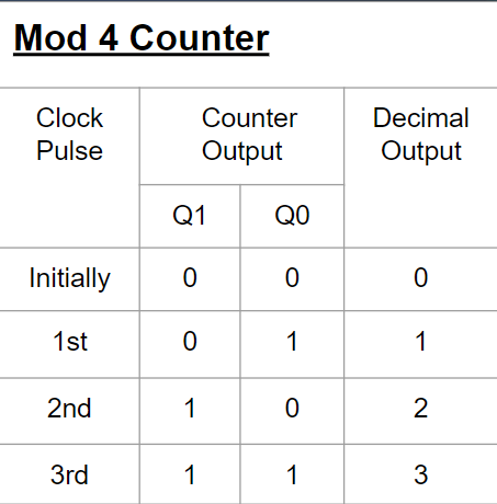
1) Mod 4 counter:
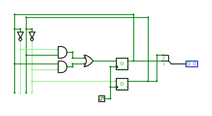
The Mod 4 counter consists of 2 D flip-flops and is controlled by a clock pulse. Every time the clock pulse changes, the counter increments by 1. This counter ranges from 0 to 3.
The truth table of the counter is as follows:
The circuit diagram of the counter is given below:
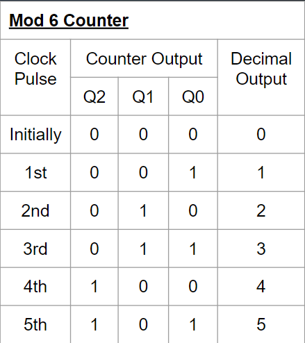
2) Mod 6 Counter:
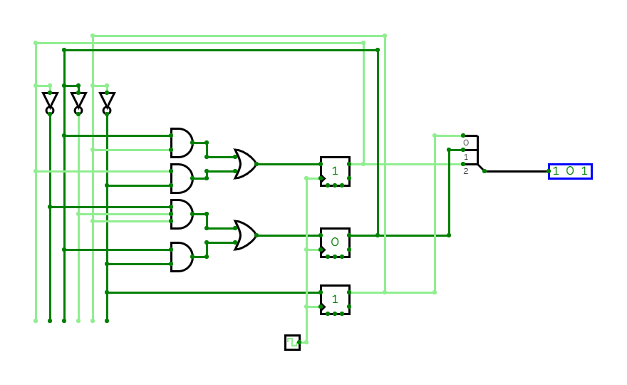
The Mod 6 counter consists of 3 D flip-flops and is controlled by a clock pulse. Every time the clock pulse changes, the counter increments by 1. This counter ranges from 0 to 5.
The truth table of the counter is as follows:
The circuit diagram of the counter is given below:
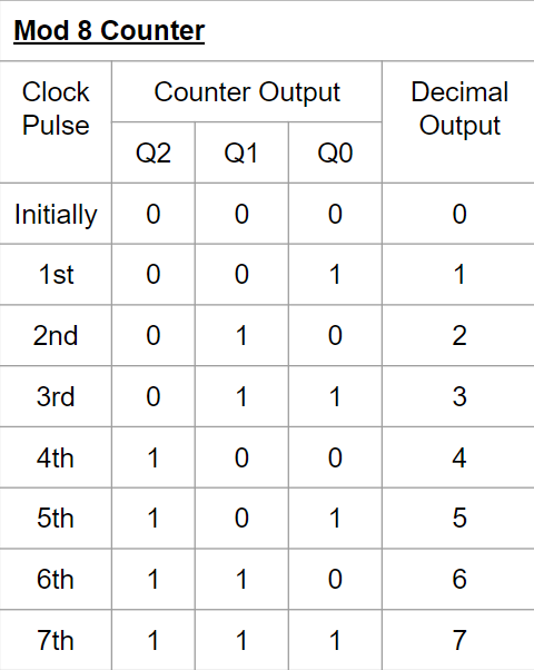
3) Mod 8 Counter:
The Mod 8 counter consists of 3 D flipflops and is controlled by a clock pulse. Every time the clock pulse changes, the counter increments by 1. This counter ranges from 0 to 7.
The truth table of the counter is given as follows:
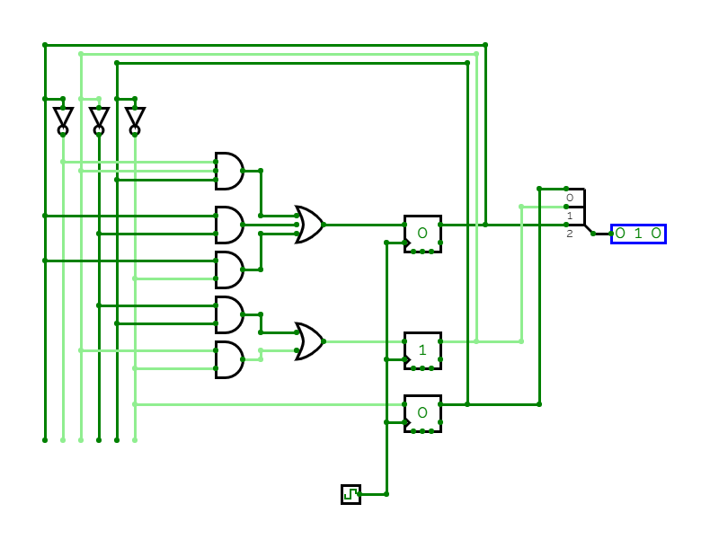
The circuit diagram of the counter is given below:
Signal Circuits
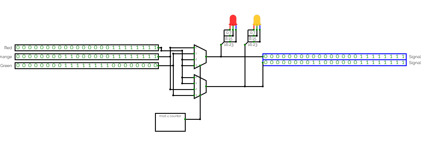
1) 2 Signal Circuit:
The 2-signal circuit is made using two 4:1 MUX and the Mod 4 counter. 2 LEDs are used to display the output. The Mod 4 counter is used as a control signal to the MUXs.
Working of the circuit: The LEDs switch between green, red and orange colors. The first LED is orange for the first clock pulse and green for the second clock pulse while the second LED is red for the first two clock pulses. While the second LED turns orange for the third clock pulse and green for the fourth clock pulse, the first LED remains red and the cycle continues.
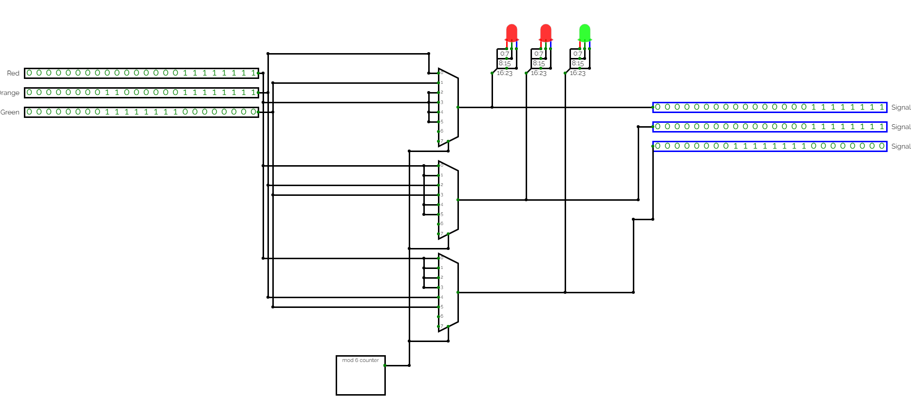
2) 3 Signal Circuit:
The 3 signal circuit is constructed similar to the 2 signal circuit. The 3-signal circuit is made using three 8:1 MUX and the Mod 6 counter. 3 LEDs are used to display the output. The Mod 6 counter is used as a control signal to the MUXs.
Working of the circuit: The LEDs switch between green, red and orange colors. The first LED is orange for the first clock pulse and green for the second clock pulse while the other LEDs remain red for the first two clock pulses. Then, the second LED turns orange and green for the third and fourth clock pulses respectively while the first and third remain red. Similarly, the third LED changes its colour to orange and red in the last two clock pulses while the other two remain red.
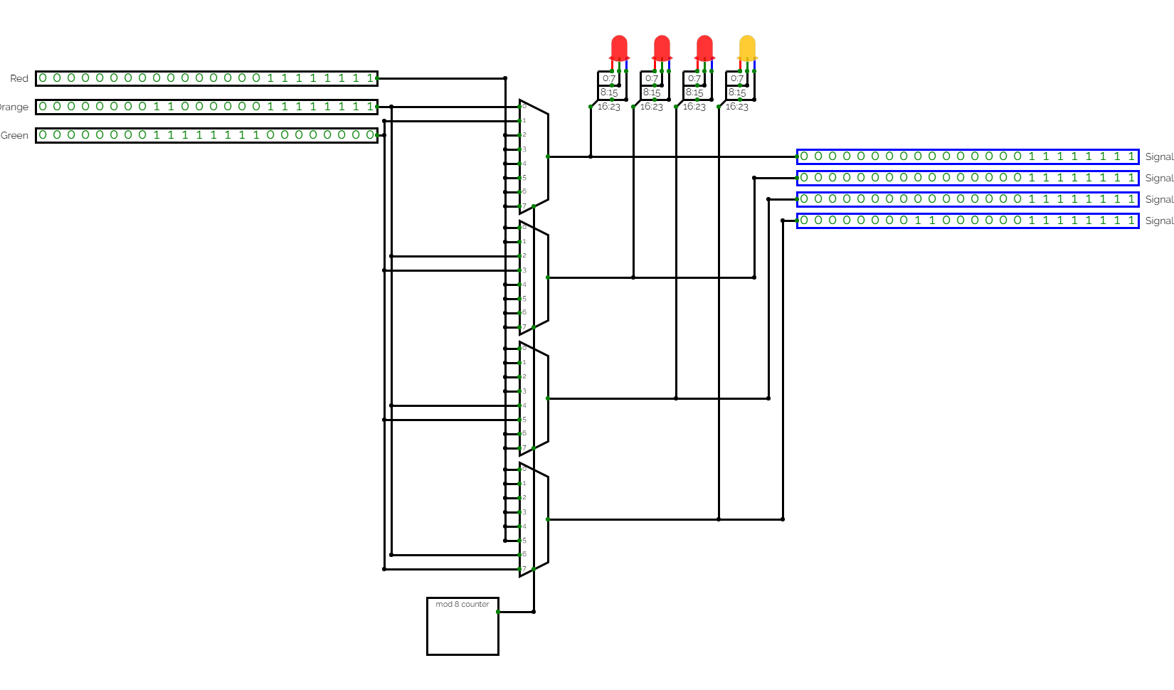
3) 4 Signal Circuit:
The 4 signal circuit is constructed similar to the 2 and 3 signal circuit. The 4-signal circuit is made using four 8:1 MUX and the Mod 8 counter. 4 LEDs are used to display the output. The Mod 8 counter is used as a control signal to the MUXs.
Working of the circuit: Similar to the 2 signal circuit and the three signal circuit, each led changes to orange and green in successive clock pulses while the other LEDs remain red.
Control Unit
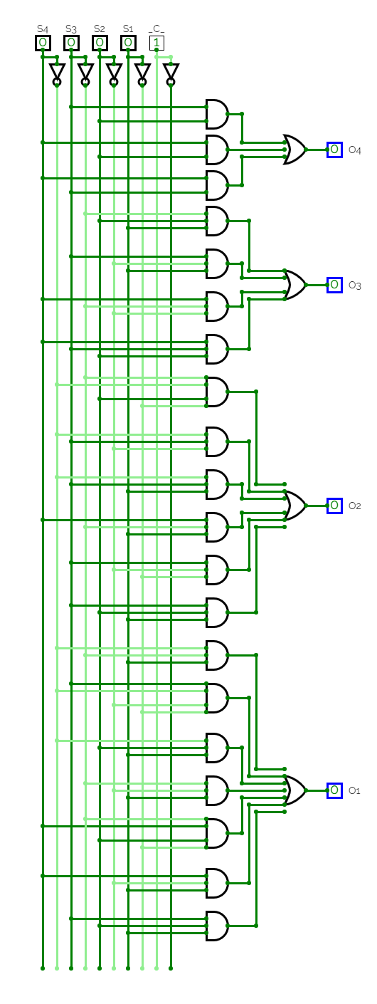
There are a total of 16 possibilities the signals can change into, based on the sensor inputs ranging from all RED to all GREEN. The above circuit gives desired output necessary to control the multiplexers in the main circuit based on the sensor inputs.
Results obtained
Main Circuit
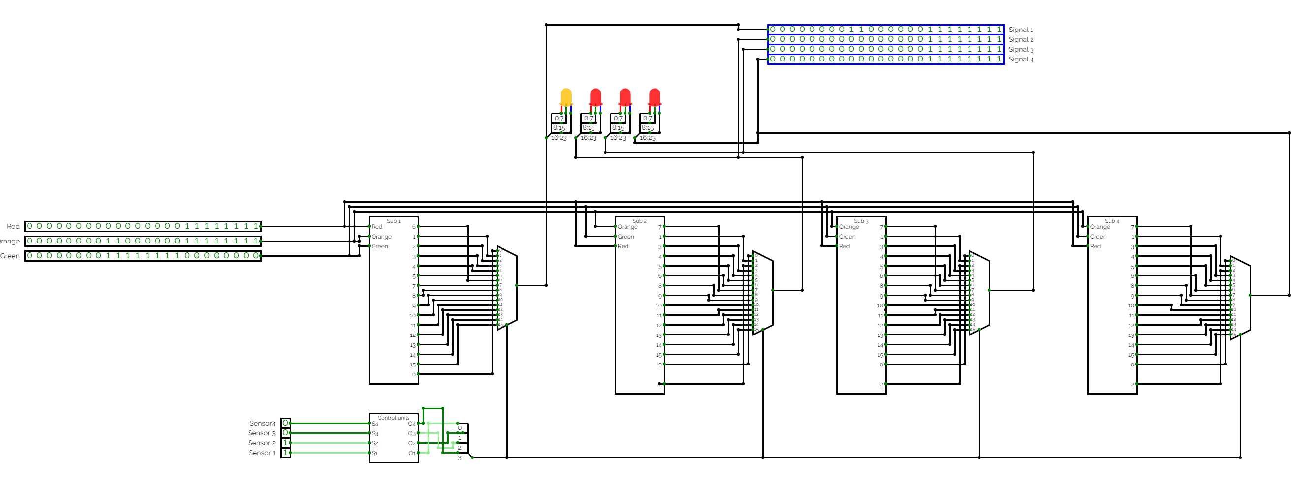
The inputs for the sub circuits Sub1, Sub2, Sub3, Sub4 are 24-bit numbers. The 24-bit numbers are a cascade of 3 8-bit numbers corresponding to the colours Blue, Green and Red. Each 8-bit number represents the intensity of the its corresponding colour ranging from 0 (meaning no intensity) to 255 (meaning maximum intensity). Here the three inputs are set to the colours Red, Orange and Green so that the RGB LED turns into either of these colours and represents a traffic signal. The inputs given to the Control unit are the sensor inputs and the output of the Control unit acts as a control signal for the multiplexers. The sub circuits Sub1, Sub2, Sub3, and Sub4 are the outputs consisting of all the 16 possibilities discussed above. The multiplexers choose an input based on the control unit and transmit it to the LEDs which represent 4 signals at a junction.
Simulated model
The sensor inputs are randomized using randomizers for each input which changes the input every 8 clock pulses (in this case 1 clock pulse is 1 second). The corresponding sensor values are shown on bottom right.