Project Mentor
- Darren Fernandes
Project Members
- Varshini C
- Shivansh J
Aim
To find the optimum fin height out of 7.3mm and 11.3mm. After finding the optimum fin height, find the optimum inlet velocity for air out of 0.5 m/s, 3.5 m/s and 6.5 m/s for maximum heat transfer.
Abstract
Analysis of two fins of A bend geometry in order to get the optimum inlet air velocity for maximum heat transfer by the fins. The analysis is completely CFD based using ANSYS- Fluent and a basic analysis of novel 3D manifolding architecture heat sink design with fin heights of 7.3mm and 11.3mm is carried out. Optimum inlet velocity and centreline temperature are found out.
Demo
Introduction
Air-cooled condensers (ACC) reduce and completely eliminate freshwater withdrawals for steam-electric plants. The performance of these ACCs is degraded on hot days by up to a 10% reduction in power production leading to higher capital expenditures. In the design modelled here, the condenser consists of an A-tent structure across the inclined walls of the A-tent. The condenser section consists of steam channels surrounded by the aluminum folded-fin assembly. Airflow is generated using very large diameter fans at the bottom of the tents. To achieve good air-side heat exchange, relatively long (~2 m) finned passages are needed due to the low heat transfer of single-phase air flow. Even after this, ACC air-side heat transfer coefficients are generally low (~35 W/m2 K). Therefore, there is a need to improve air-side heat exchange that will reduce total thermal resistance and translate into reductions in steam condensation temperatures.
A lot of studies have been conducted on the analysis of fins and their efficiencies. This study deals with the CFD analysis of A tent fins on ANSYS Student with motivation and specifications drawn from reference.
Fins are extended surfaces which are added to facilitate heat transfer between a hot and a cold body. While most fins are generally added to increase heat loss, we need greater efficiency of fins in order for the fins to transfer heat better. Extended surfaces lead to an increased heat loss with an increase in area. However, the efficiency of the fins is inversely proportional to length. As we need to facilitate heat transfer, a balance between fin size, heat transfer and efficiency has to be struck. In the following study of natural and forced convection heat transfer, temperature at center-line and temperature contours over an interval of time are observed and plotted.
Modelling
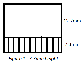
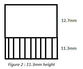
ANSYS-Fluent Student version was used for the given study. Various parameters and dimensions of the size of fin and design are observable in Figure 1. The base size of the fins was 1m length and 1m breadth. The fin thickness was taken as 5mm and fin height for two different runs was taken as 7.3mm and 11.3mm. The base height of the fins is kept constant at 12.7mm.
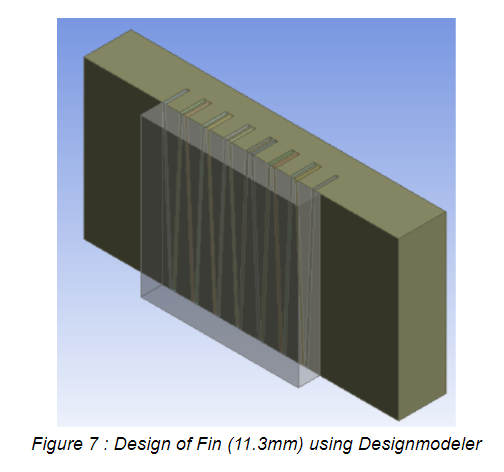
Geometry
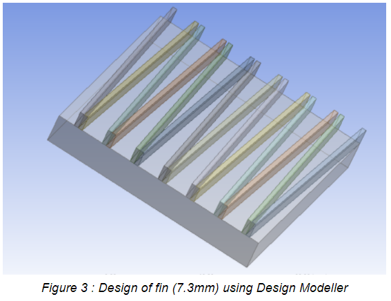
The geometry of the inner pin was designed using Ansys Design-Modeler. The XY plane is the plane of drawing the diagram with extrude feature used along +z direction for the base and -z for the fins.
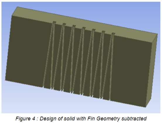
Then, a surrounding solid envelope was added to it with the fin geometry being subtracted from the solid geometry. This was to be the domain of air flow.
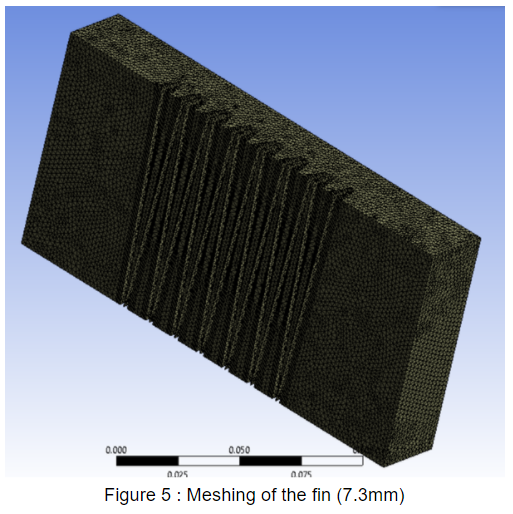
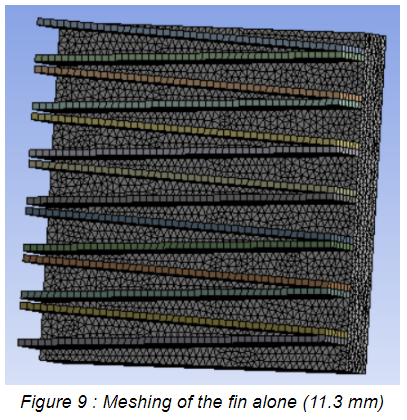
Meshing
The next step was meshing of the Design. Here element size was fixed at 0.002m. An inflation of maximum 10 layers was created for the edges of the fins. There was a need to limit the mesh size and inflation as the limit of number of elements as well as nodes is 512000 for setup in the ANSYS student version.
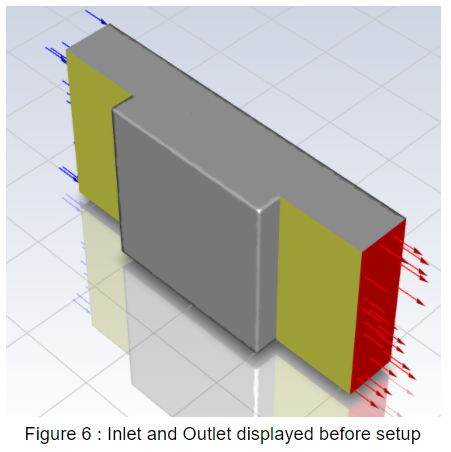
Then, four named selections were made :
- Inlet
- Outlet
- Fin boundary
- Wall boundary
Inlet : It is the wall of the envelope from where the air enters. It is a wall parallel to the YZ plane.
Outlet : It is the wall of envelope from where the air exits. It is also parallel to the YZ plane.
Fin Boundary : The fins as surfaces are taken for doing surface analysis of heat transfer.
Wall Boundary : The wall or base of fin is taken for doing surface analysis.
Set-up
In the set up, the Fin was set as solid and the surrounding envelope was set as fluid. The fin material was set as aluminium and the fluid was set as air. Boundary Conditions :
- Inlet velocity : 0.5 m/s
- Temperature of fin wall : 400 K
Mesh interfaces were set to a coupled wall. Then, the system was initialized. Three planes were created at different distances from the z-axis for the study of temperature profile.
- Z = -0.00815 m
- Z = -0.009 m
- Z = -0.01 m
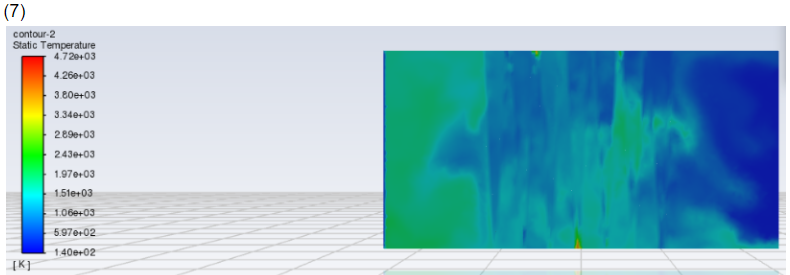
Contours were added to these planes for the study. These contours were set to represent temperature.
Then, the number of iterations was set at 500 and results were calculated.
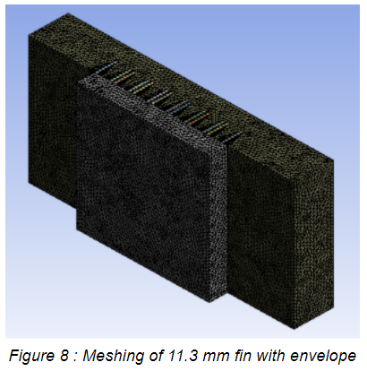
The above steps were repeated for Fin Height 11.3mm and different flow velocities of air.(3.5m/s and 6.5m/s). Diagrams 7,8,9 represent the meshing and input analysis.
Results
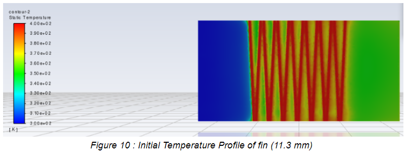
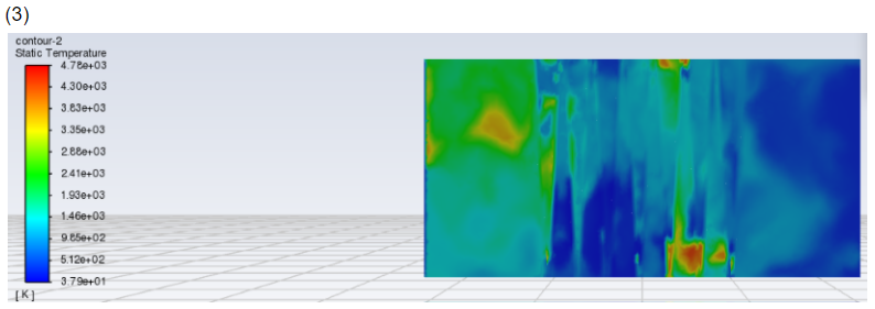
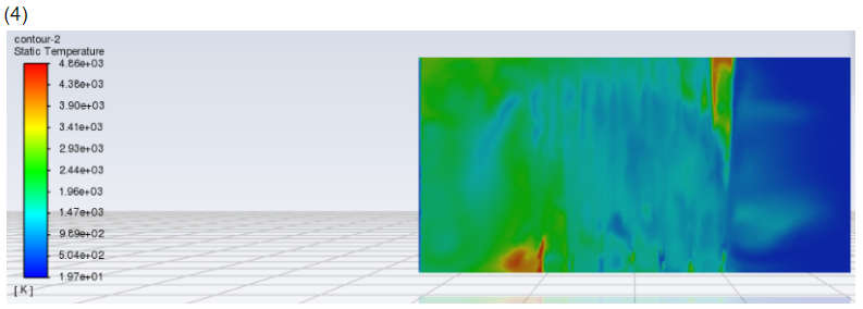
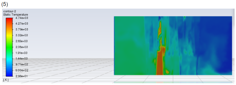
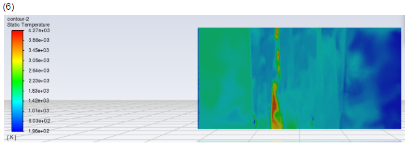
This was the Initial Temperature Profile along plane 2.
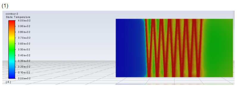
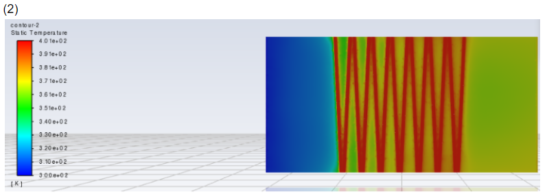
The Temperature Profile along Plane 2 captured at discrete points of time looked as follows :
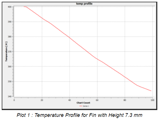
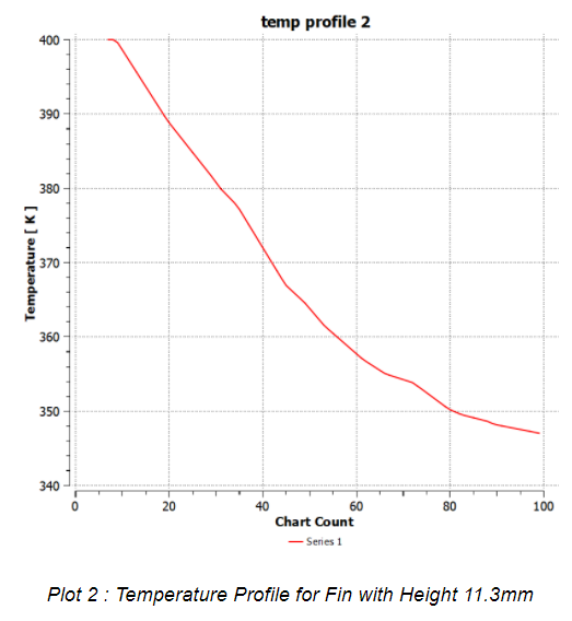
A line was drawn along the z-axis such that it passed through a fin normally. It was extended to a distance of 0.015m along the z-axis. Then, a plot of Temperature versus Distance was plotted for both Fins (7.3 mm and 11.3 mm) at inlet air velocity as 0.5 m/s.
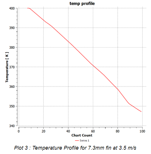
We pass air as three different velocities through the 7.3mm fin.
- 0.5 m/s
- 3.5 m/s
- 6.5 m/s
Again, a line was drawn along the z-axis such that it passed through a fin normally. It was extended to a distance of 0.015m along the z-axis. Then, a plot of Temperature versus Distance was plotted for all three cases.
Plot 1 is the Temperature versus Distance graph for the 7.3 mm fin at inlet air velocity 0.5 m/s.
Conclusions
- From Plot 1, we can see that the 7.3mm fin system reaches 344 K at the end 0.015 m.
- From Plot 2, we can see that the 11.3mm fin system reaches 347 K at the end 0.015 m.
As system 1 reaches a lower temperature for the same length, it can be concluded that Fin1 has better heat transfer characteristics. Therefore, it is concluded that the optimum fin height is 7.3 mm.
Now we compare the heat transfer characteristics for different inlet velocities.
- From Plot 1, we can see that the system with inlet air velocity 0.5 m/s reaches 344 K at the end 0.015 m.
- From Plot 3, we can see that the system with inlet air velocity 3.5 m/s reaches 347 K at the end 0.015 m.
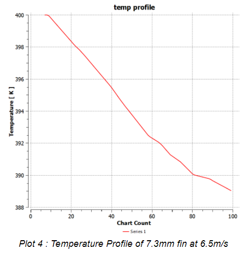
- From Plot 4, we can see that the system with inlet air velocity 6.5 m/s reaches 346 K at the end 0.015 m.
As the system with 0.5 m/s inlet air velocity reaches a lower temperature for the same length, it can be concluded that 0.5 m/s is the optimum inlet air velocity.
Therefore, taking all the observations into considerations, we conclude that the best fin for use is one with height 7.3mm operated with 0.5 m/s inlet air velocity.
References
- Investigation of 3D manifold architecture heat sinks in air-cooled condensers by Chirag R. Kharangatea , Will Libeerb , James Palkoc , Hyoungsoon Leed , Jessica Shie , Mehdi Asheghib , Kenneth E. Goodsonb Link
- (Heat Transfer) Colaço, Marcelo J.Cotta, Renato M. Orlande, Helcio R. B. Öziik, M. Necati - Finite Difference Methods in Heat Transfer, Second Edition-CRC Press (2017)
- Heat Transfer by Yunus A. Cengel
- Q. Liu, L. Xia, M. Hu, X. Li, Z. Mi, J. Jia, Positive impact of a tower inlet cover on natural draft dry cooling towers under crosswind conditions, Appl. Therm. Eng. 139 (2018) 283–294, Link
- H.A. El-Sheikh, S.V. Gurimella, Enhancement of air jet impingement heat transfer using pin-fin heat sinks, IEEE Trans. Compon. Packag. Technol. 23 (2000) 300–308, Link
- C.J. Meyer, Numerical investigation of the effect of inlet flow distortions on forced draught air-cooled heat exchanger performance, Appl. Therm. Eng. 25 (2005) 1634–1649, Link