Mentors
-
Aryan Manoj Murthy
-
Afraz Siddiqui
Members
-
Prudhvi Nallagatla
-
Shiven Dutt Sharma
-
Yash
-
Shreesha
Aim
The project aims to build a two axes gimbal using Arduino, MPU 6050, some servo motors and parts modelled in Fusion 360, and 3D printed to make up the gimbal’s body.
Introduction
A gimbal is a mechanical support system that enables an object to rotate around an axis while remaining stable. This device has three/two servo motors arranged perpendicular to one another, which enables the central object to maintain its position regardless of any movements made by the support. In this setup, an MPU 6050 sensor captures 6-degree orientation data (roll, pitch, angles), which is processed using an Arduino microcontroller.
The Arduino computes corrections to compensate for any internal inaccuracies in the sensor readings. The Arduino controls two servo motors placed on the gimbal’s roll and pitch axes to preserve the desired orientation. These motors make precise adjustments to counteract any deviations in the sensed orientation, ensuring the stability of the mounted object.
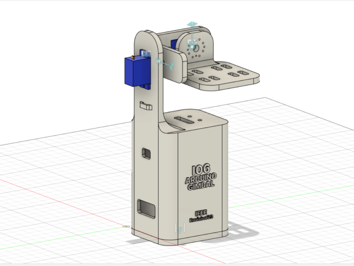
The physical setup for the gimbal system is designed using Fusion 360 software. The setup serves as the foundation for the gimbal system after getting printed.
Implementation
We created the gimbal model using Fusion 360 and then printed it using a 3D printer. After that, we attached the Arduino, MPU 6050, and servo motors to the gimbal. While doing that, we wrote and tested the code for all the components.
Working of the Components
Mpu6050 sensor basics
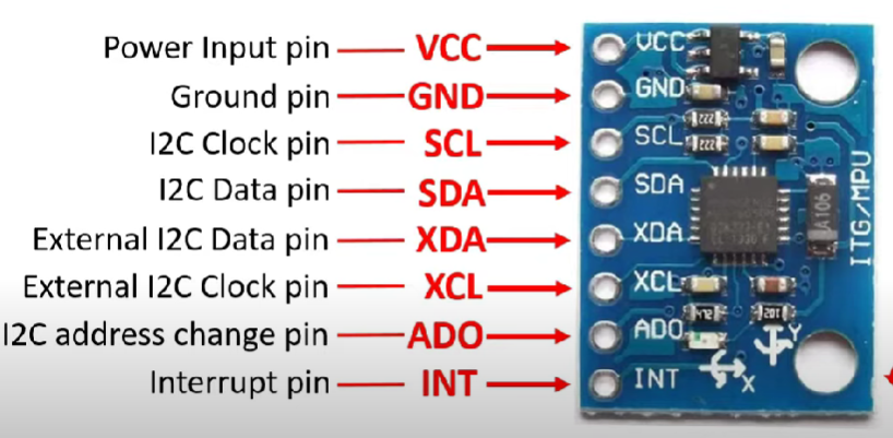
It is a six-axis motion sensor that combines a three-axis gyroscope, a three-axis accelerometer, and a digital motion processor. It is based on the I2C protocol. The most crucial part of MPU6050 is the MPU6050 IC(microelectromechanical system) which changes the voltage according to the axis position. We have used five pins of MPU6050 (out of the eight pins), namely - +Vcc, which takes input from 3.3V to 5V, Gnd, SCL - I2c pin, SDA - I2c pin, INT - notifies about available data.
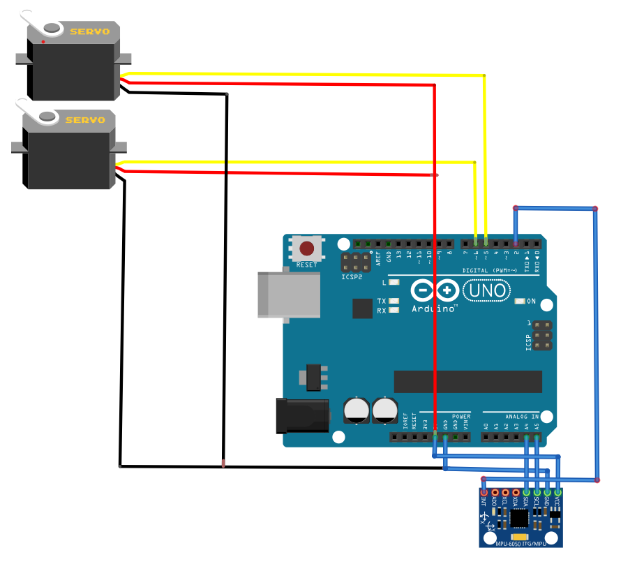
Circuit Model and connection of MPU6050 to Arduino.
To complete the system, we created a circuit model using Fritzing software. Fritzing allowed us to design the electrical connections between the Arduino, MPU 6050 sensor, and servo motors. This circuit model represented the wiring and ensured proper connectivity between the components.
Programming and Testing in Arduino
We used two important libraries in our project: I2Cdev.h(credits-Gymneus) and MPU6050.h(credits-Jeff Rowberg), along with built in servo.h library. We used these libraries to connect the Arduino and the MPU 6050 sensor. With their pre-built functions and methods, we could interact with the sensor using the I2C protocol. To begin our development, we used the code Jeff Rowberg created. It provided a solid foundation for our project. By building upon this code, we focussed on the functionalities and customisation required for our gimbal system.
Integrating Mpu6050 with processing IDE
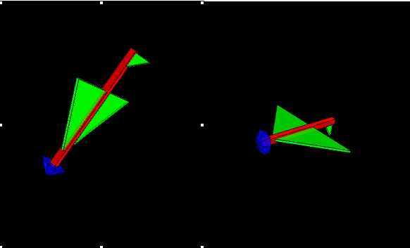
In order to visualise the working of the MPU6050 sensor, we used the Processing IDE. By combining the ‘Output_Teapot’ code with the processing application, we created a 3D simulation. This simulation helped us to observe and interpret the orientation data provided by the MPU6050 sensor.
Conclusion
As part of this project, we have developed a functional gimbal that operates in real time. Through the process, we gained knowledge about both Arduino and Fusion 360. However, we discovered that the gimbal code could be improved with additional time and understanding.
Future Work
We are working on improving the functionality of our gimbal by adding a servo motor that will operate on the Z-axis. This will provide more control and precision when using the gimbal. We are optimising the code of the gimbal to make it more efficient.