Mentors
- Kruti Deepan Panda
- Vineeth Narayan
Members
- Harsh Nahata
- Akheel Muhammed
- Bote Sharavani Rajesh
- Rishee K
Abstract
Microprocessors are some of the most widely used components in circuits. They are present in laptops, desktops, mobiles, cars, and many more devices. Every microprocessor has an essential element called the ALU. The ALU performs the basic arithmetic and logical operations in a circuit. The aim of this project is to design and simulate a 32 bit ALU, using a hardware description language (Verilog). The ALU consists of 9 different operations, based on operation code (OP code) the ALU decides which operation is to be done among various 9 operations. Basically, it is a combinational circuit that takes 32-bit data as input and gives 32-bit output by performing specified arithmetic and logical operations.
Designing the ALU
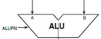
ALU is a combinational circuit taking two 32-bit data words A and B as the input, and producing a 32-bit output Y by performing the specified arithmetic or logical operation on the A and B inputs. The operation to be executed by the ALU is specified by a 6-bit control input. The ALU also has a Z flag and an N flag as output. The Z flag signifies whether or not the output is zero. The N flag signifies whether or not the output is negative. The logical symbol of the ALU is shown below.
The ALU consists of 9 different operations .The operations and their Boolean expressions are listed in following table -
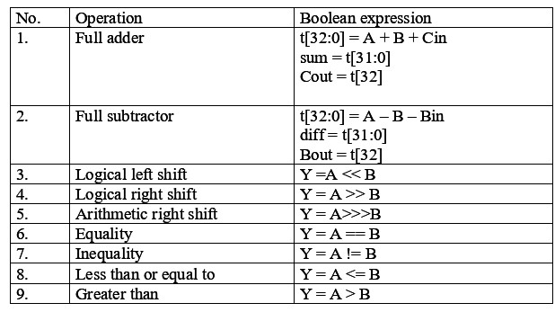
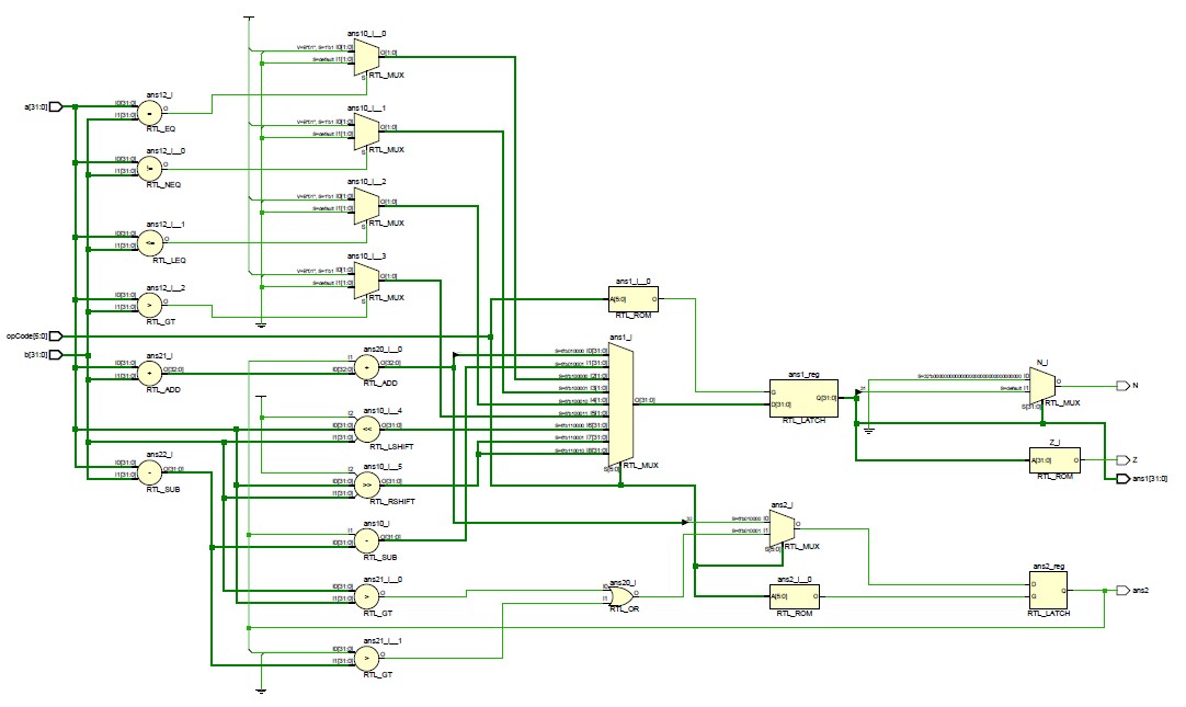
The following are the design of the nine components of the ALU namely -
- FULL ADDER: we have assigned the total as the sum of the two numbers and a carry the 33rd bit will be assigned to the carry bit and the first 32 bits as the output.
- FULL SUBTRACTER: we have assigned the total as the difference between the two numbers and the borrow in. The borrow bit is assigned under an if condition the input ’a’ is less than ’b’ then the borrow bit is 1 bit or else 0.
- EQUAL TO: we have used the logical operator(“==”) to check equal to which gives 1 if true or else 0.
- NOT EQUAL TO: we have used the logical operator(“!=”) to check not equal to which gives 1 if true or else 0.
- LESSER THAN OR EQUAL TO: we have used the logical operator less than or equal to (“<=”)to check the two inputs and return 1 if true or else 0.
- GREATER THAN OR: we have used the logical operator greater than(“>”) to check the two inputs and return 1 if true or else 0.
- LOGICAL RIGHT SHIFT: we have used the logical operator logical right shift(“»”) to shift the input.
- LOGICAL LEFT SHIFT: we have used the logical operator logical left shift (“«”)to shift the input.
- ARITHMETIC RIGHT SHIFT: we have used the operator arithmetic right shift(“ »>”)to shift the input.
Simulation
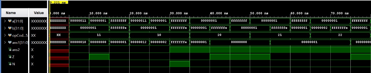
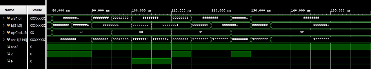
The ALU design is simulated using the ALU test bench. The test bench consists of several different inputs for two variables and a case selection input to determine which operation is to be executed by the ALU. The test bench then simulates these inputs on the ALU design module and generates outputs in the form of a wave. The simulation has been generated using the “Xilinx Vivado” platform. There are 9 different operations in the ALU simulated using the test bench starting from subtraction, addition, equality check, not equal to check, less than or equal to check, greater than check, left shift, right shift, and arithmetic right shift. The case selection input which determines the operation to be executed is represented by the variable opCode in the waveform. The value of opCode for each operation (in hexadecimal) is as follows -
| Operation | Opcode |
|---|---|
| Subtraction | 0x11 |
| Addition | 0x10 |
| equality check | 0x20 |
| not equal to check | 0x21 |
| less than or equal to check | 0x22 |
| greater than check | 0x23 |
| left shift | 0x30 |
| right shift | 0x31 |
| arithmetic right shift | 0x32 |
These operations take 2 inputs represented by ‘a’ and ‘b’.The output generated by them is then stored in the register variable ‘ ans1’ The N and Z outputs are flags that show whether the output ans1 is negative or not and zero or not respectively.
Results
The ALU design supported nine operations – Addition, Subtraction, Equality check between 2 numbers, not equal to check between 2 numbers, ’greater than and less than ’ or ’equal to’ check between 2 numbers, logical left shift, logical right shift, and lastly arithmetic right shift. The design was simulated using the test bench and after a successful run produced the following outputs.