Mentors
- Deepanshu Gupta
Members
- Venugopal R
- Harshak Sachdeva
- Umesh Ruthwik
- Vinay Kumar
Acknowledgements
- Rohan Rao
Aim
Design and implementation of a three-level boost converter with maximum power point tracking (MPPT) applications in Photo-Voltaic(PV) Cells.
Introduction
The need for MPPT arises from the fact that renewable energy sources such as solar and wind have variable output power that is affected by various environmental factors. Thus, to maximize the power output, it is necessary to track the maximum power point (MPP) of the energy source. Traditional boost converters suffer from limited efficiency, high voltage stress on the switch and output diode, and large output ripple.
On the other hand, a three-level boost converter offers a higher voltage conversion ratio, reduced voltage stress on the switches and output diode, and lower output ripple. It achieves these benefits by using an additional voltage level, which reduces the voltage stress on the switch and output diode. Additionally, by using MPPT algorithms, the three-level boost converter can track the MPP of the input energy source and optimize the power output.
Experimental results show that the proposed three-level boost converter with MPPT applications achieved a peak efficiency of 97.5 percentage , which is higher than traditional boost converters with MPPT. Overall, this project demonstrates that the three-level boost converter with MPPT applications is a promising solution for renewable energy sources.
DC-DC boost converter
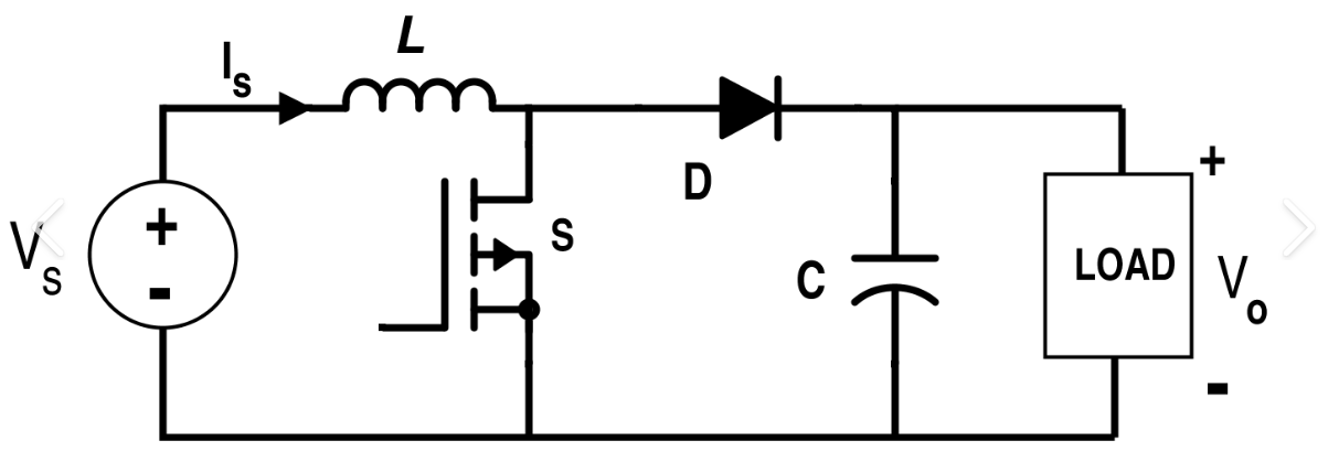
A traditional DC-DC boost converter is shown in figure 1. It consists of a capacitor,inductor and diode, with a switching transistor, a MOSFET. The output of boost converter is stepped up by a factor, which is dependent on the duty cycle and the switching frequency of the MOSFET.
The MOSFET is turned on and off at a high frequency, because of which, the inductor charges and discharges. When the switch is turned on the diode is reverse biased, hence, the circuit acts as two independent circuits, where the inductor charges and the capacitor discharges.
Three level boost converter
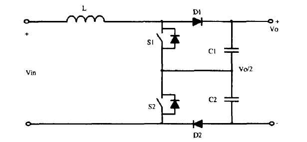
The following image depicts a three-level boost converter. In this, a capacitor voltage divider is used in parallel with the load. To maintain the symmetry and balance of the converter, the capacitance of both capacitors must be equal. This in turn makes the center point voltage as half of the output voltage.
The TLBC has four different states of operation, depending on which of the switches are on or off at a given time. This makes the TLBC more dynamic and can provide higher gain than a traditional boost converter.
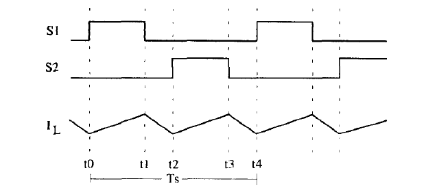
Region 1 - Vin > Vo/2
When the required output is less than twice the input voltage, then we apply the operating mode as shown in figure 3. In this operation mode, duty cycle D < 0.5
The switch S1 is turned on for time DT and then turned off throughout the cycle. During this time, S2 is off. The switch S2 is turned on from T/2 to T/2 + DT.
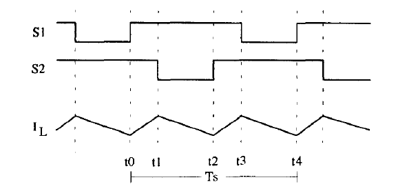
Region 1 - Vin < Vo/2
When the required output is more than twice the input voltage, then we apply the operating mode as shown in figure 4. In this operation mode, duty cycle D > 0.5
the switch S1 is turned on for time DT and then turned off throughout the cycle. The switch S2 is turned on from T/2 to T/2 + DT. In this switching mode, both the switches are on for a short period of time, but the duty cycle of eacg switch remains the same.
Maximum Power Point Tracking
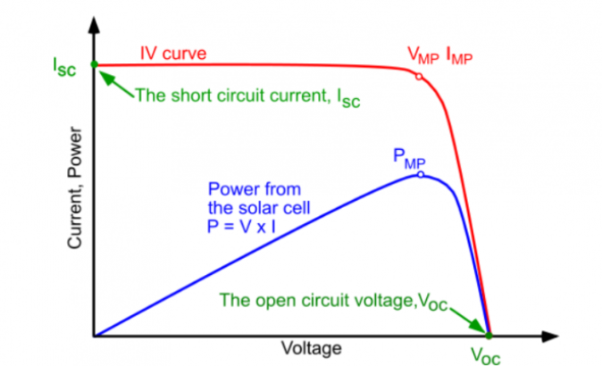
The PV cell exhibits a distinct Current vs Voltage characteristic curve, as depicted in Figure 5. This curve illustrates the short circuit current and open circuit voltage of the solar cell, with the maximum power point (MPP) denoting the point on the curve where the power output is at its highest. The Power vs Voltage curve reveals that the output power of a PV cell surges to a peak before diminishing as the voltage fluctuates between 0 and the open circuit voltage. To ensure optimal power output, the PV cell should operate at the voltage corresponding to the MPP (Vmp). However, the MPP is subject to variations in the PV cell, temperature, shading conditions, and irradiance.
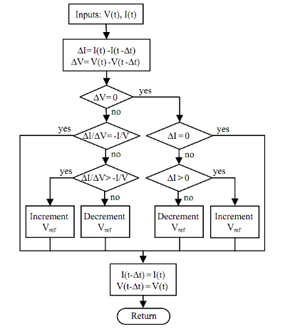
In this MPPT method operate by comparing the instantaneous power output of the PV array with its incremental power, which is the rate of change of the power with respect to the change in the panel’s voltage. The method is based on the observation that at the MPP, the incremental power is zero. Therefore, the algorithm is designed to track the MPP by adjusting the system’s voltage based on the sign of the incremental power.
If the incremental power is positive, it implies that the system is not yet operating at the MPP and the system’s voltage needs to be increased. On the other hand, if the incremental power is negative, it implies that the system has already passed the MPP and the system’s voltage needs to be decreased. The algorithm adjusts the voltage until the incremental power becomes zero, which indicates that the system is at the MPP.
A DC-DC converter is implemented as an MPP tracker for PV modules, with the PV module connected to the input of the converter. MPP tracking is performed by adjusting the duty cycle of the converter.
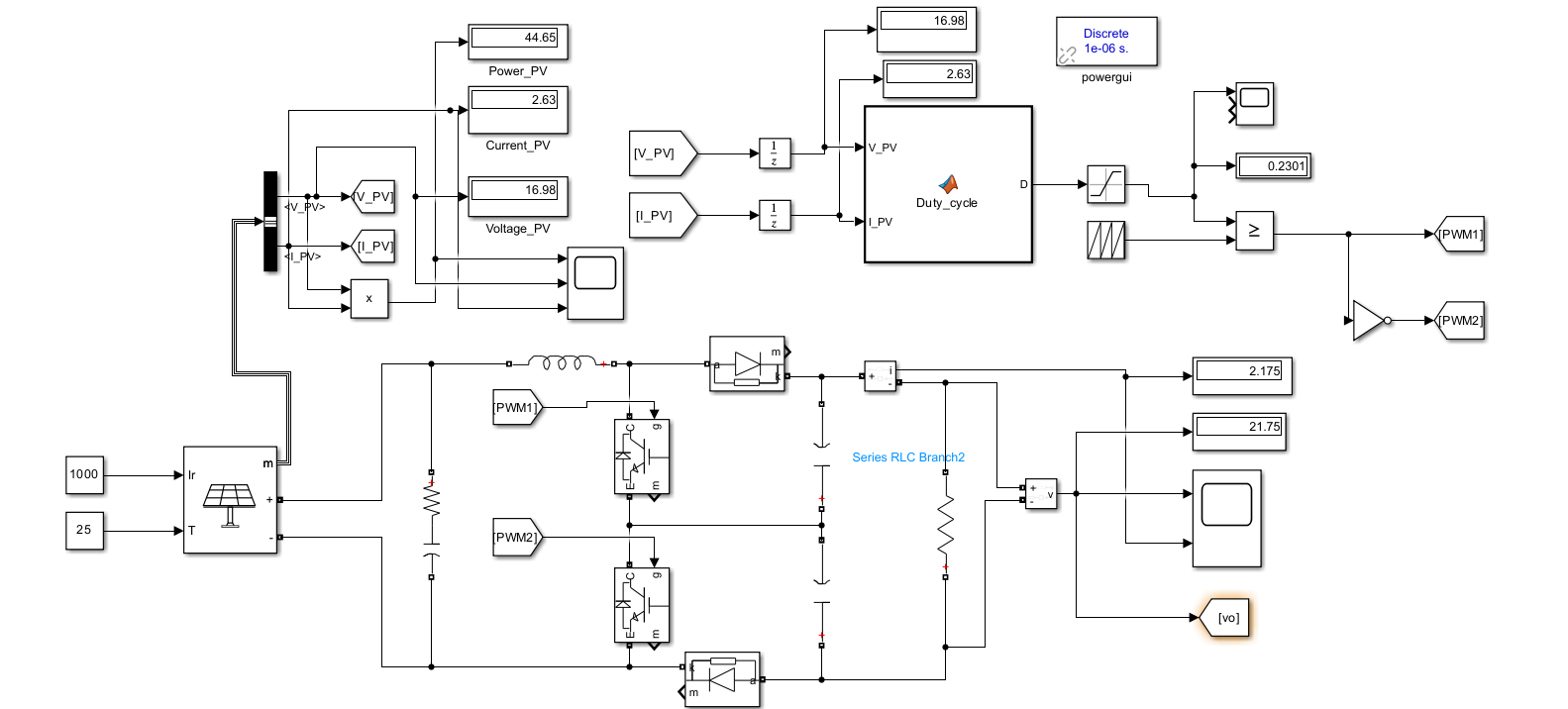
Simulation and results
In this simulation, we will model a TLBC using Simulink blocks for MPPT applications. The voltage and current inputs from the PV panel are fed into a MATLAB function generator, which utilizes the Incremental Conductance (INC) method to dynamically adjust the converter’s duty cycle to track the MPP. The PWM generator is then employed to generate the switching signals for the converter.
For the simulation, we utilized a PV panel with the following specifications:
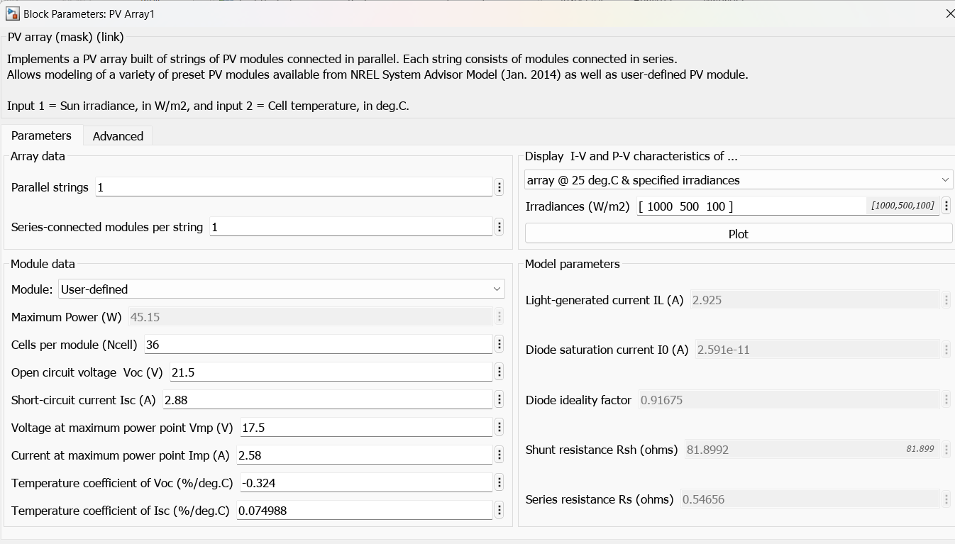
For this PV panel, we must perform MPP tracking using the Incremental Conductance method. To achieve this, we use a MATLAB function generator to generate the TLBC’s duty cycle to track the MPP.
The MATLAB function was coded using the INC algorithm to vary the duty cycle to achieve the MPP. The initial duty cycle was set to be 0.5. The MATLAB code for the function is as follows:
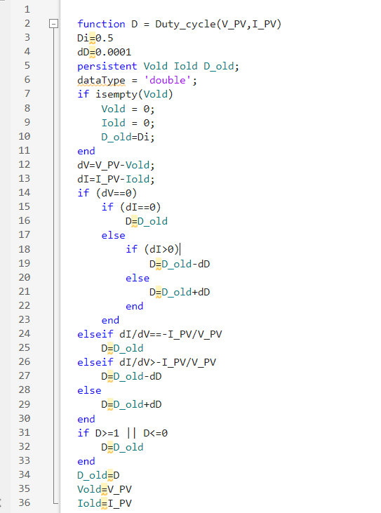
The voltage and current signals from the PV panel are used as inputs for this function, which operates in closed-loop control and finds the MPP point, but oscillates around it once steady state is reached.
For the values of the inductor and capacitors, we have selected 0.5mH and 20uF respectively. These values were calculated to achieve a boost with 5\% voltage ripple and 20\% current ripple. We have set the resistance value at 10 Ohms.
The scope data for the output voltage and power from the PV panel is shown below.
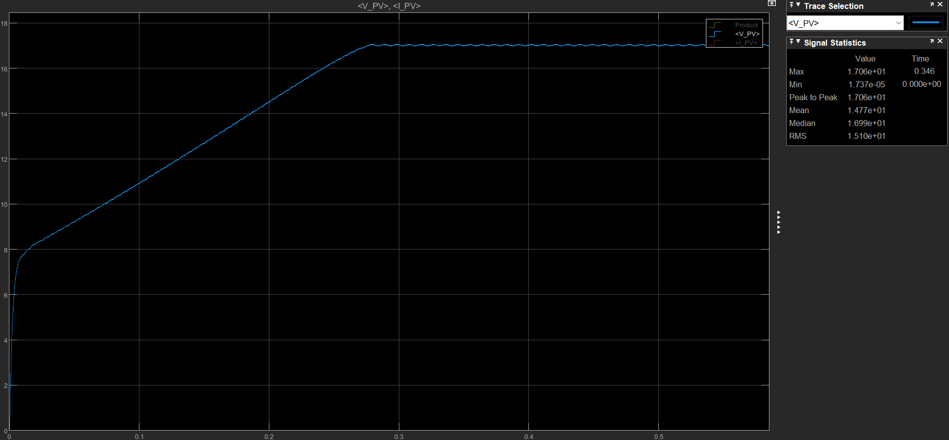
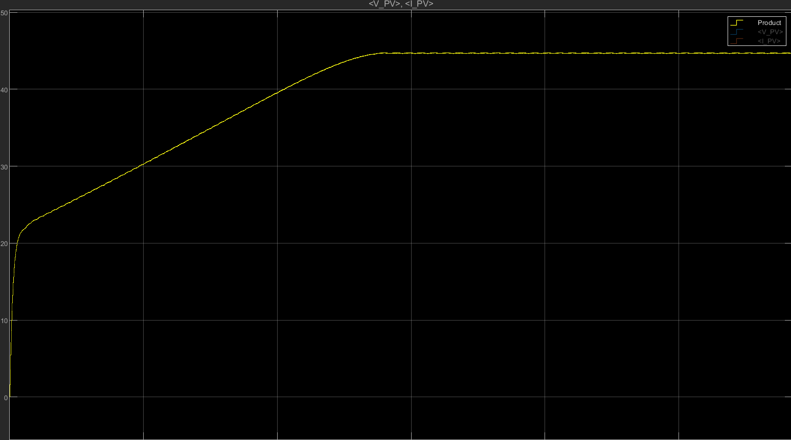
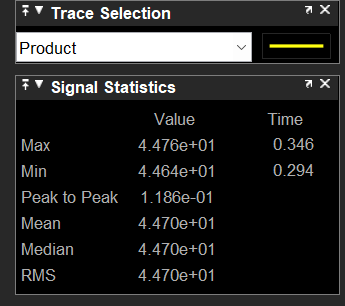
As shown in the scope data, the output power is 44.7W with a peak-to-peak ripple of 100mW. This indicates that the designed TLBC model is able to perform MPPT. The efficiency of this TLBC in finding the MPP is 99%
Conclusion
In this project, a three-level boost converter with MPPT applications has been designed, implemented, and tested. The results show that the proposed system offers higher efficiency and improved performance compared to the traditional boost converter with MPPT. The MPPT algorithm successfully tracks the maximum power point of the solar panel, resulting in maximum power extraction from the source. The three-level boost converter offers more voltage steps and a wider operating range than the traditional boost converter, making it a better topology for MPPT applications.
The proposed system can be extended in several ways. First, the proposed system can be integrated with a battery storage system to store the excess power generated from the solar panel. Second, the proposed system can be used in combination with other renewable energy sources such as wind and hydro to develop a hybrid energy system. Finally, the proposed system can be scaled up to a larger capacity for commercial and industrial applications, such as electric vehicles and hybrid electric vehicles to improve their performance and efficiency.
In conclusion, the three-level boost converter with MPPT applications is a better solution for renewable energy systems than the traditional boost converter with MPPT. The proposed system offers higher efficiency and improved performance, and its applications are vast and varied. Therefore, the proposed system has the potential to play a significant role in the transition towards a sustainable energy future.