Mentors
- Saee Sholapurkar
- Himanshu Garud
Members
- Harish B
- Rayner Menzes
Aim
To study the mechanism of a string drive and implement the knowledge in building a String bicycle model.
Introduction
Using strings instead of chains is a non-conventional bicycle technology. String bicycles use a rope and pulley-driven system instead of chain-driven mechanisms to drive the cycle. It is an efficient mechanism because power transmission between the pedal and the rear wheel is a pure rolling motion with minimal frictional losses. Additionally, it guarantees a hassle-free ride with negligible chances of chain-tripping and no concerns about oiling. Assembling and disassembling are much more manageable, making the bicycle easy to carry in compact spaces.
Project Work
Working of String drive
The crankset is part of the bike that your legs push around to turn the rear wheel. It consists of the stringring (which string goes around) and the crank arms (which the pedals attach to).
A circular spring facilitates the retraction motion of the string during pedaling. During forward motion, the string uncoils and provides a torque on the rear hub, loading the spring and leading to the wheel’s movement. As the string is fully uncoiled, it needs to be coiled back to be available for the next rotation cycle of the crankset. This is done by the spring.
The design is such that the forward motion of the wheel is not restricted even during the rewinding of the string. This is possible due to the use of a ratchet sprocket. The sprocket works with the spring and disengages power during rewinding.
String Bicycle Animated YouTube
Design
Cam Path
A cam and follower profile was generated on Fusion360 using references from available models. A motion study was performed to analyze the path.
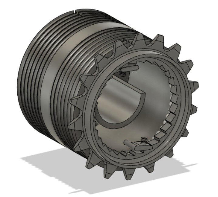
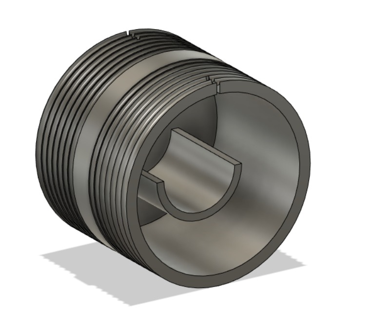
Casing for the Rear Sprocket
A special casing was designed on Fusion360 to house the ratchet sprocket and the spring, which uncoils and rewinds the spring on the rear.
Analysis
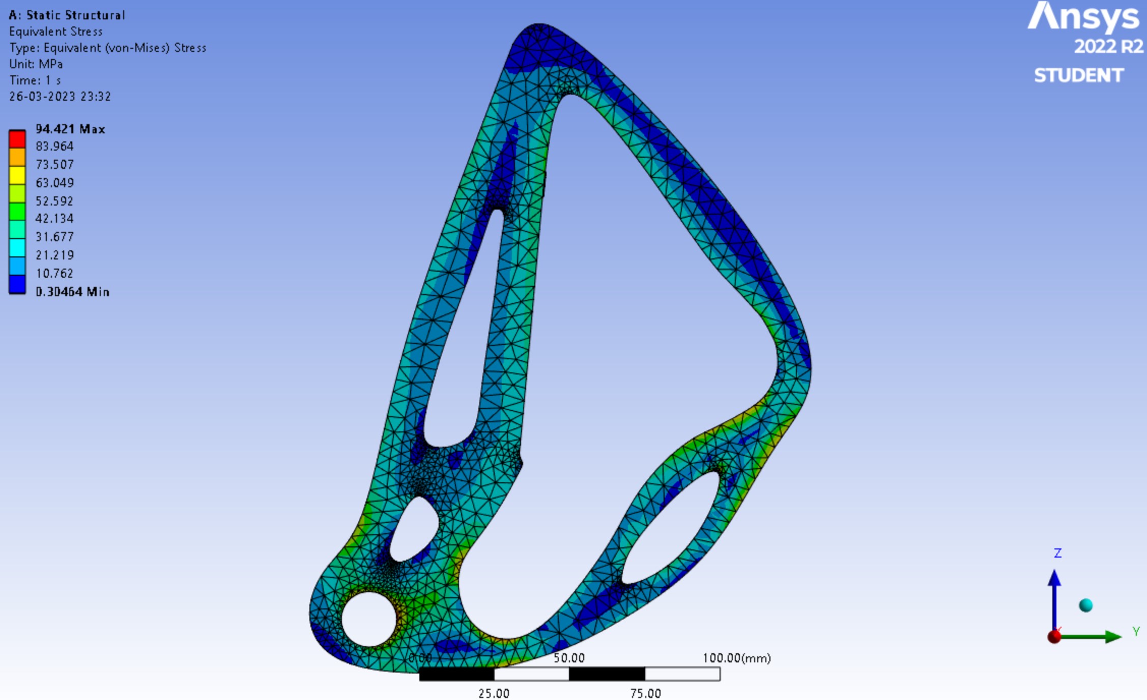
Structural Analysis
Structural analysis was performed on the selected sprocket design, given boundary conditions (extreme case) and Von Mises stresses were calculated after meshing in Ansys.
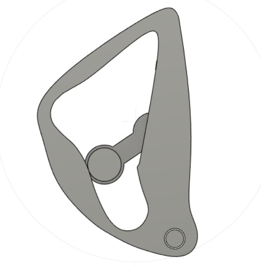
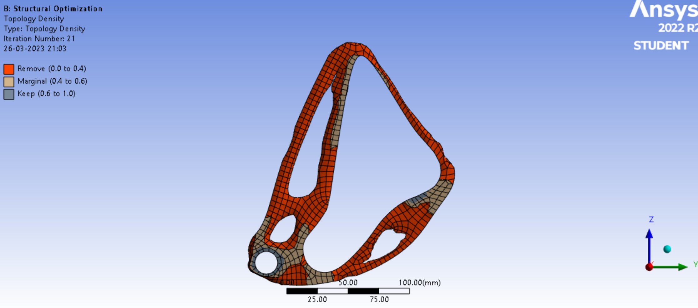
Topology Optimisation
To optimize the distribution of material, i.e remove material to reduce weight and save costs, we used topology/structural optimisation on Ansys. Material was removed where stresses were less and a good balance between strength and affordability was attained. Smoothening of the material was done in places where the material was removed to aid in manufacturing. This was followed by structural analysis to double check. Factor of safety for the final design obtained was 2.6.
Material selection
Here we used the Weighted Property Indices method to suit the problem specification with weights for cost, tensile strength and density of suitable materials.

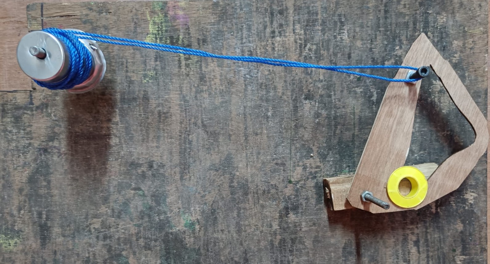
Prototyping
A prototype was built using scrap material that best replicated the actual components used while building the model. It was constructive in giving the project members a better feel of the mechanism being developed and the important point to be noted for further project development.
Modelling
CNC Machining
Stainless steel sheet of thickness 2mm was laser cut according to the final front sprocket design. 2mm thickness was taken as it is lighter and has good stiffness.
3D Printing
Casing for the back sprocket which includes grooves for the string to sit on was designed and 3D printed using PLA which is also one of the most environmentally friendly 3D printing materials.
Conclusion
The string drive mechanism was thoroughly studied through hands-on experience during construction of a functioning model.
Skills acquired:
- CAD Modelling using Fusion360
- Topology Optimization using Ansys
- Exposure to Manufacturing processes- 3D printing, CNC machining
- Handling of power tools in the mechanical laboratory