Mentors
- Anannya Rao
- Harish Ravi Kale
- Rupankar Das
Members
- Ashish Vinay Pastay
- Vedangi Nishane
- Siddalingeshwar Patil
- Bhavya Jain
Aim
Hydrodynamic modeling and study of the thermo-hydraulic performance of various shell and tube heat exchanger configurations
Introduction
A heat exchanger may be defined as an equipment which transfers the energy from a hot fluid to a cold fluid, with maximum rate and minimum investment and running costs. In a heat exchanger the temperature of each fluid changes as it passes through the exchangers, and hence the temperature of the dividing wall between the fluids also changes along the length of the exchanger. Shell and tube heat exchangers are indirect contact devices wherein heat transfer is achieved as the fluids pass separately through the shell and tube bundles, by means of conduction and convection. These heat exchangers are designed to achieve optimal heat load through a range of flexible variations. Geometric parameters (e.g. diameter, length, number of tubes, etc.) may be modified to increase the surface area for heat transfer, while fluid flow significantly affects performance parameters such as the heat transfer rate and effectiveness Shell and tube heat exchangers(STHE) are the most common type of heat exchangers used in the present scenario. Heat exchangers are widely used equipment in various industries such as power generation and transportation, refrigeration industry and chemical process industries because it suits high pressure application. Hence in order to increase its performance various research have been conducted mainly in the field of design enhancement of it. Presented in this project is comparison for several shell and tube heat exchangers with segmental baffles and fins.
Modeling
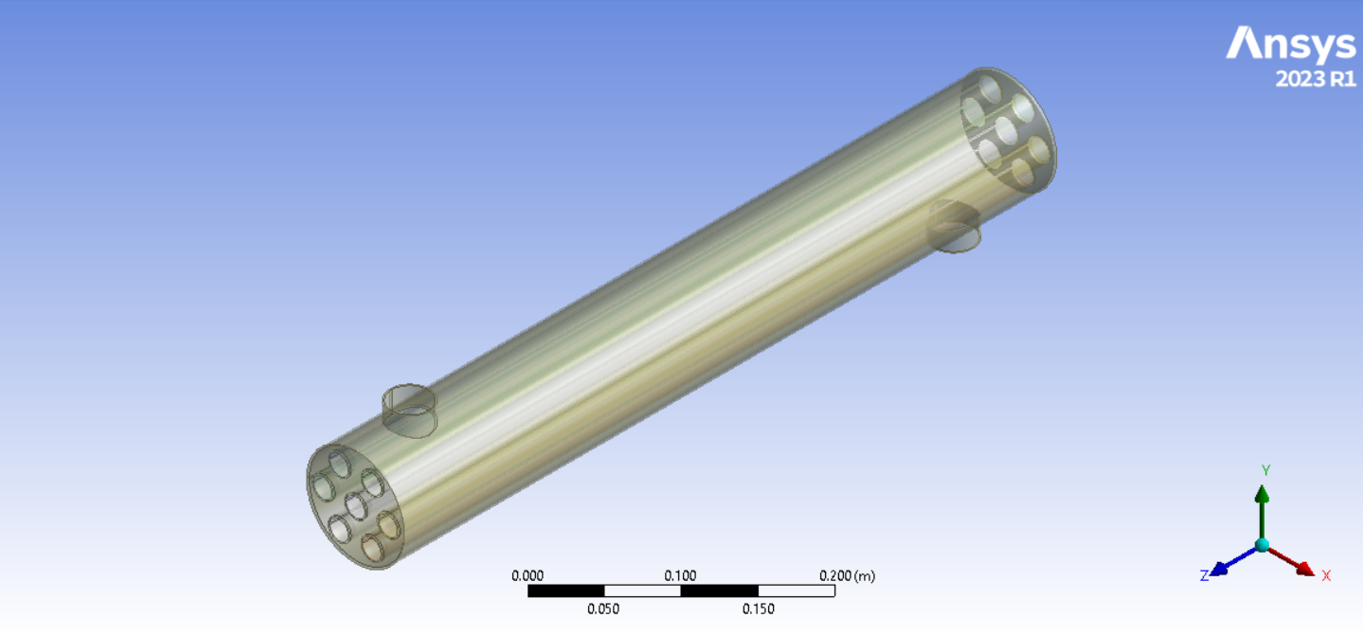
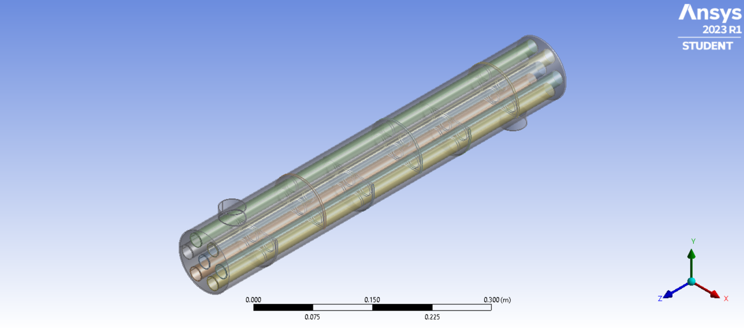
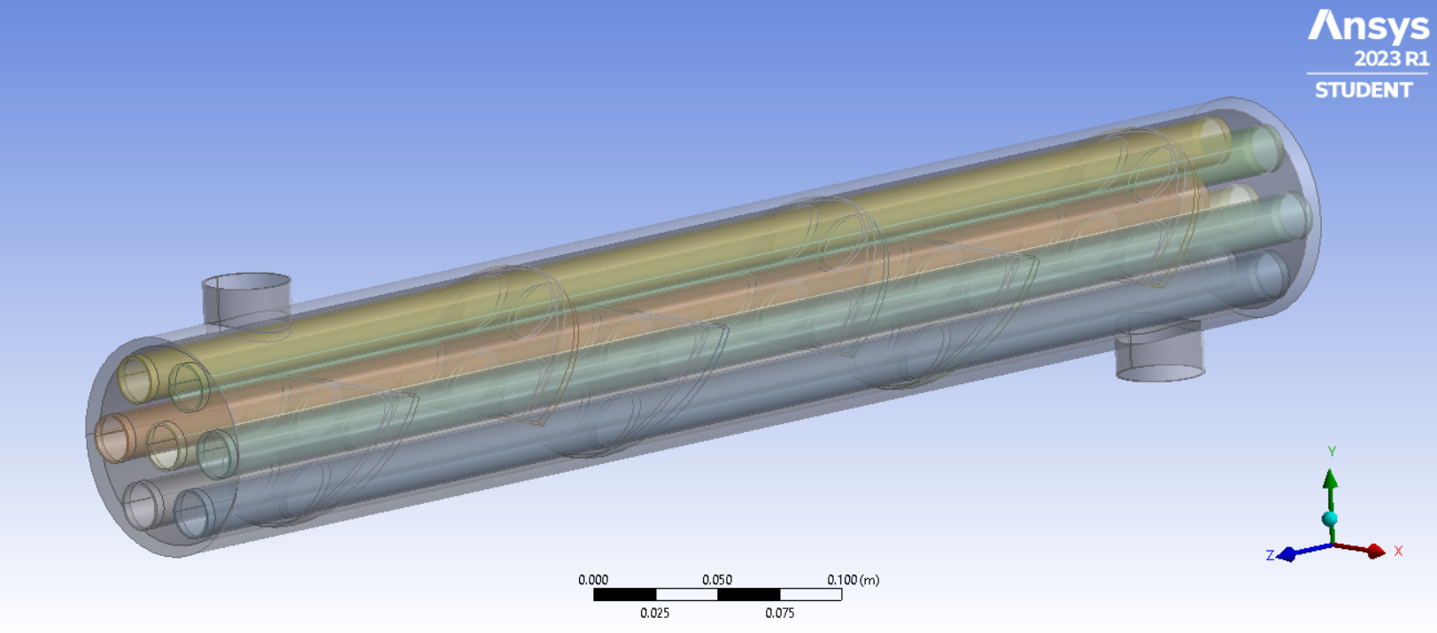
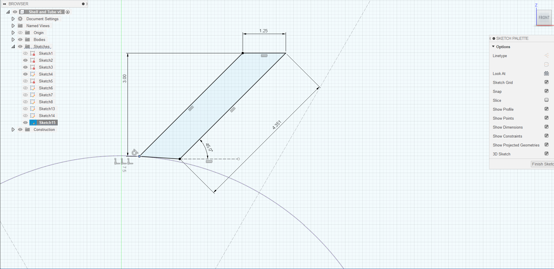
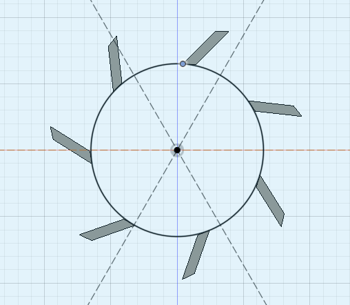
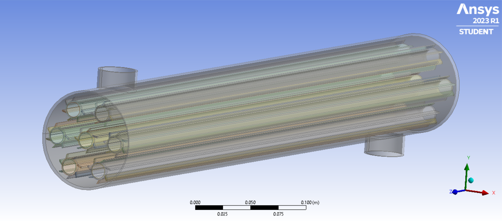
In this study the shell and tube heat exchanger with six baffles are placed along the shell in alternating orientations with cut facing up, cut facing down, etc., in order to create flow paths across tube bundles. The geometric model was compared by varying baffle inclination i.e 0°,20° , 40°. Shell and Tube Heat Exchanger with fins was also modeled in Fusion 360.The geometry modeling was done using software called Fusion 360 as it is easy to model Heat exchanger in 3D modelling software.
The Fusion 360 model was exported to Ansys Fluent in .step format and CFD Analysis of the designs was carried out.
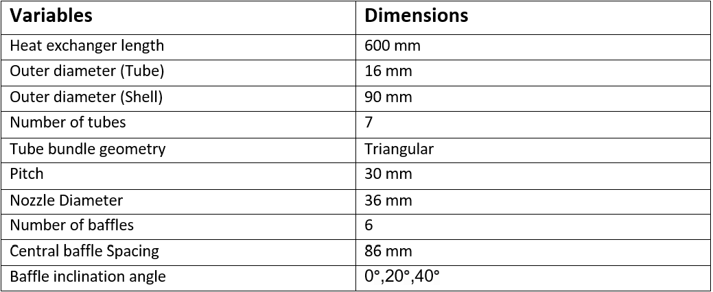
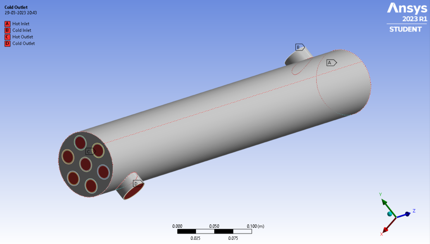
Geometry
The different heat exchanger designs were modeled in Fusion 360. The thickness of tubes is taken to be 1 mm and thickness of shell is taken as 3 mm.The dimensions of the heat exchanger are:
The different shell and tube heat exchanger configurations modeled in Fusion 360 are:
Meshing
The element size for the mesh was taken to be 10mm. The edges of shell inlet,shell outlet,tube inlet and tube outlet were sized to 70 divisions. The mesh size and the number of divisions were arrived at by performing Grid Independent Study(GIS) on Shell and Tube Heat Exchanger with a single tube under the same boundary and flow conditions.
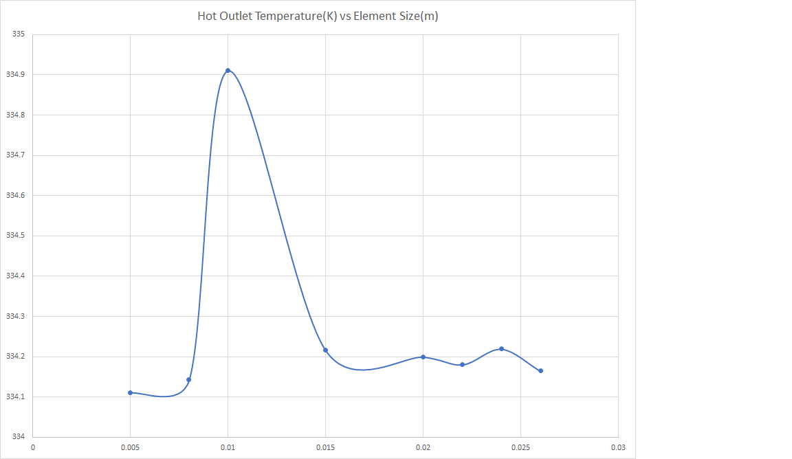
From the above plot obtained from Grid Independent study on a single tube heat exchanger,we can conclude that the smallest mesh element size, after which the outlet temperature becomes independent of element size, is 10mm.
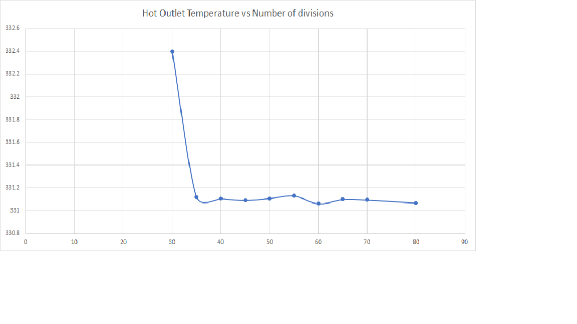
From the above plot, we can conclude that the number of divisions after which there is no significant change in the outlet temperature of hot fluid is 70.
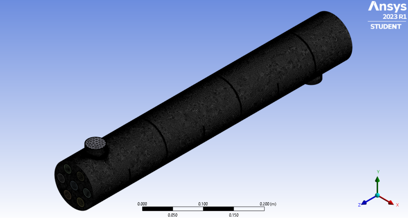
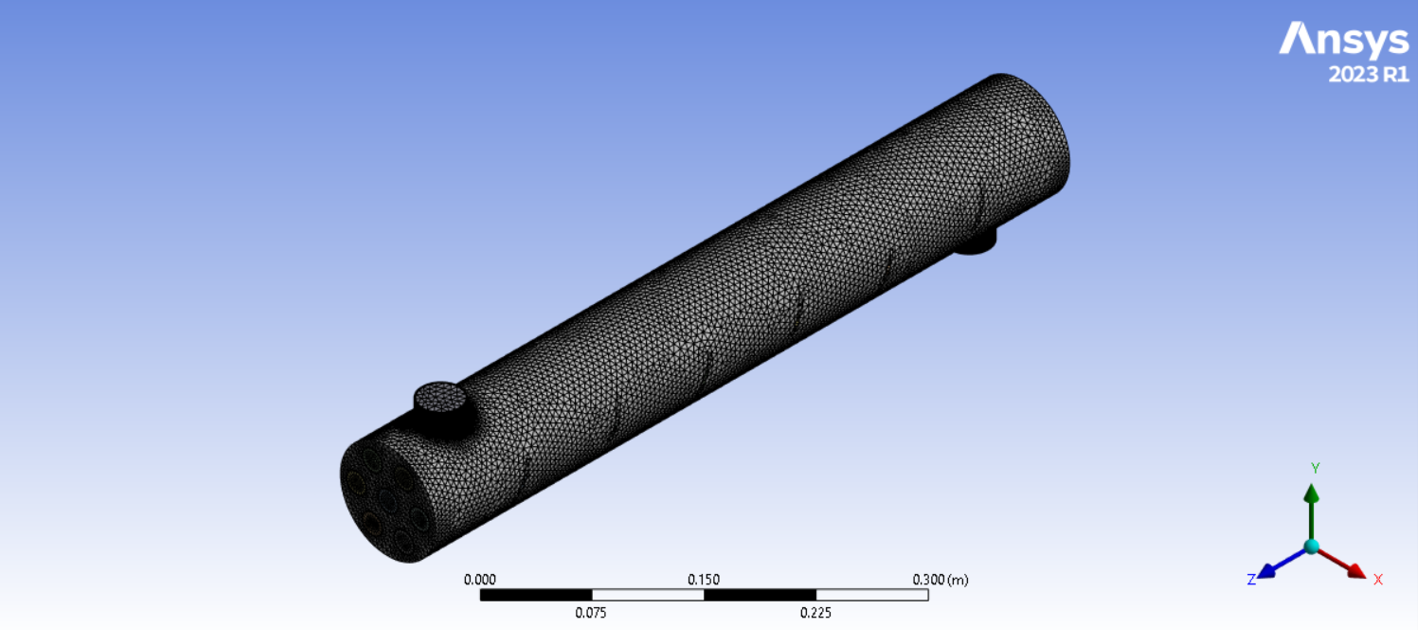
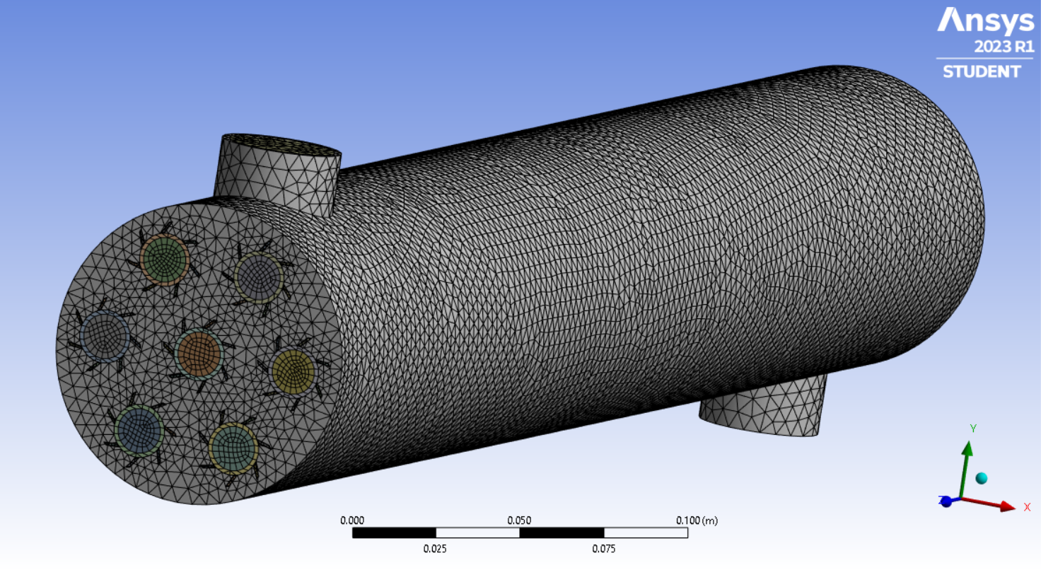
The mesh was generated for shell and tube heat exchanger with 7 tubes by taking the appropriate element size and number of divisions, as obtained from the Grid Independent Study.
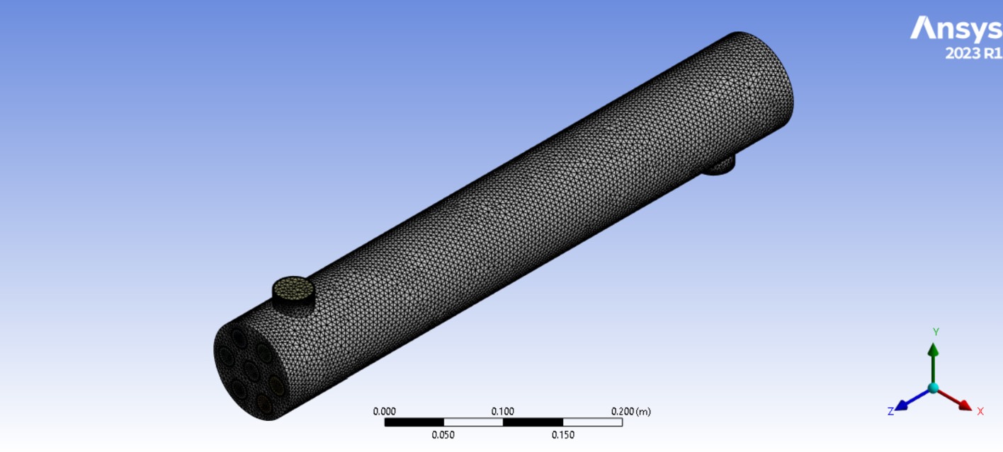
The named selection used for the above generated mesh are:
The mesh element size was taken as 10mm and edge sizing was done for inlets and outlets of hot and cold fluids,with the number of divisions as 70. Body sizing was applied to baffles with element size of 0.18 mm.
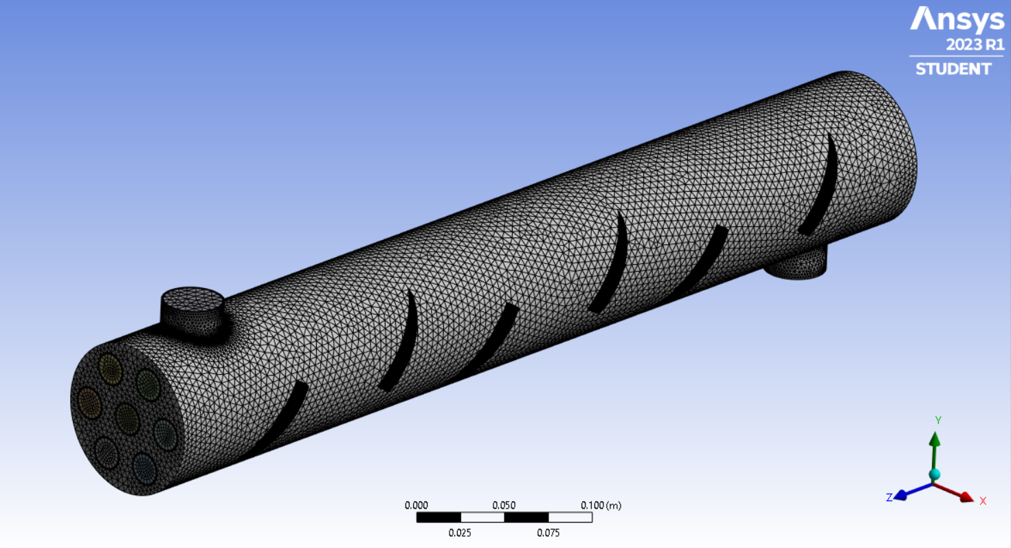
The mesh element size for Shell and Tube Heat Exchanger with fins was taken to be 5mm. Body sizing for fins with element size of 2mm was chosen. The mesh around the boundary of the fins was inflated with 8 maximum layers. The parameters for mesh refinement were decided by assessing the quality of the mesh(aspect ratio,skewness,element quality) at different values of the parameter.
Setup
Model
The SST k-w model was used to model flow inside the heat exchanger and the energy equation was turned on. Water as fluid and Aluminium as the solid material was chosen.
Boundary conditions
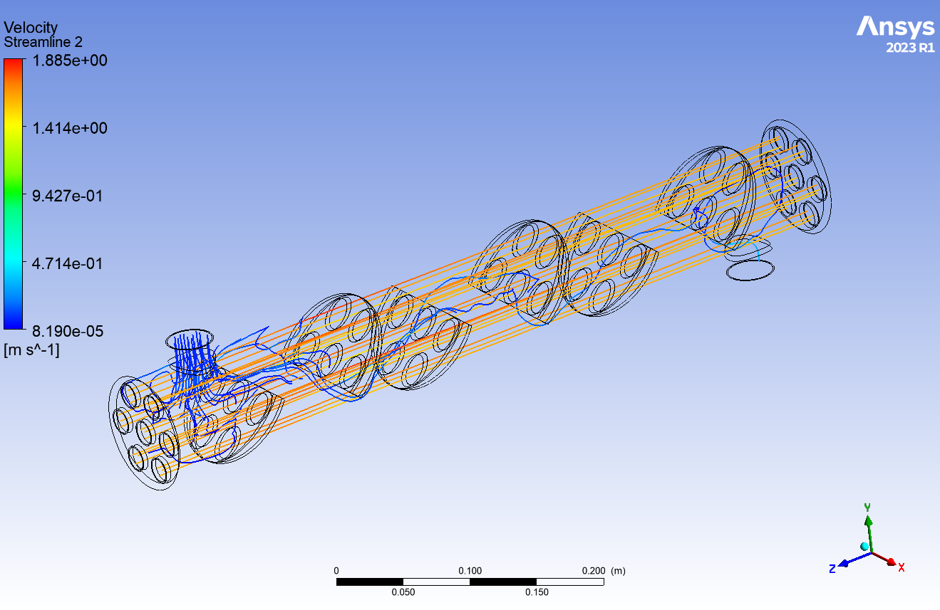
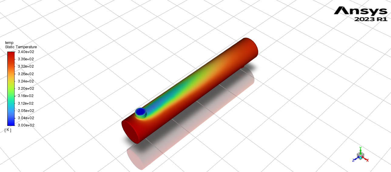
The inlet velocity of the cold fluid was kept constant i.e. 0.0787m/s, whereas velocity of hot fluid was kept constant i.e. 1.594 m/s. The outlet pressures were kept default i.e. atmospheric pressure. The outlet boundary condition was set to a pressure outlet with atmospheric pressure as the reference. The hot fluid temperature at the inlet was 340K and cold fluid inlet temperature was kept at 300k. The other wall conditions were defined accordingly. The surrounding air temperature was kept at 300K.
Solution Methods
The solution methods were set as follows: Scheme = Simplec Gradient = Least Square Cell Based Pressure = Second Order Upwind Momentum = Second Order Upwind Turbulent Kinetic Energy = Second Order Upwind Turbulent Dissipation Rate = Second Order Upwind Energy= First Order Upwind
Solution Control
Under relaxation factors the parameters are: Pressure = 0.7 Pa Density =1 kg/m3 Body forces =1 kg/m2.s2 Momentum= 0.2 kg-m/s Turbulent kinetic energy= 1 m2/s2
Solution Initialization
Residuals were set to 1e-6. Solution initialization was “standard method” and solution was initialized from an inlet with 300k temperature.
Contours and Animation
The temperature contour was added and animation for the temperature contour for each iteration was added.
Calculations
The calculation was run for 100 timesteps and outlet temperature of hot and cold fluid was computed.
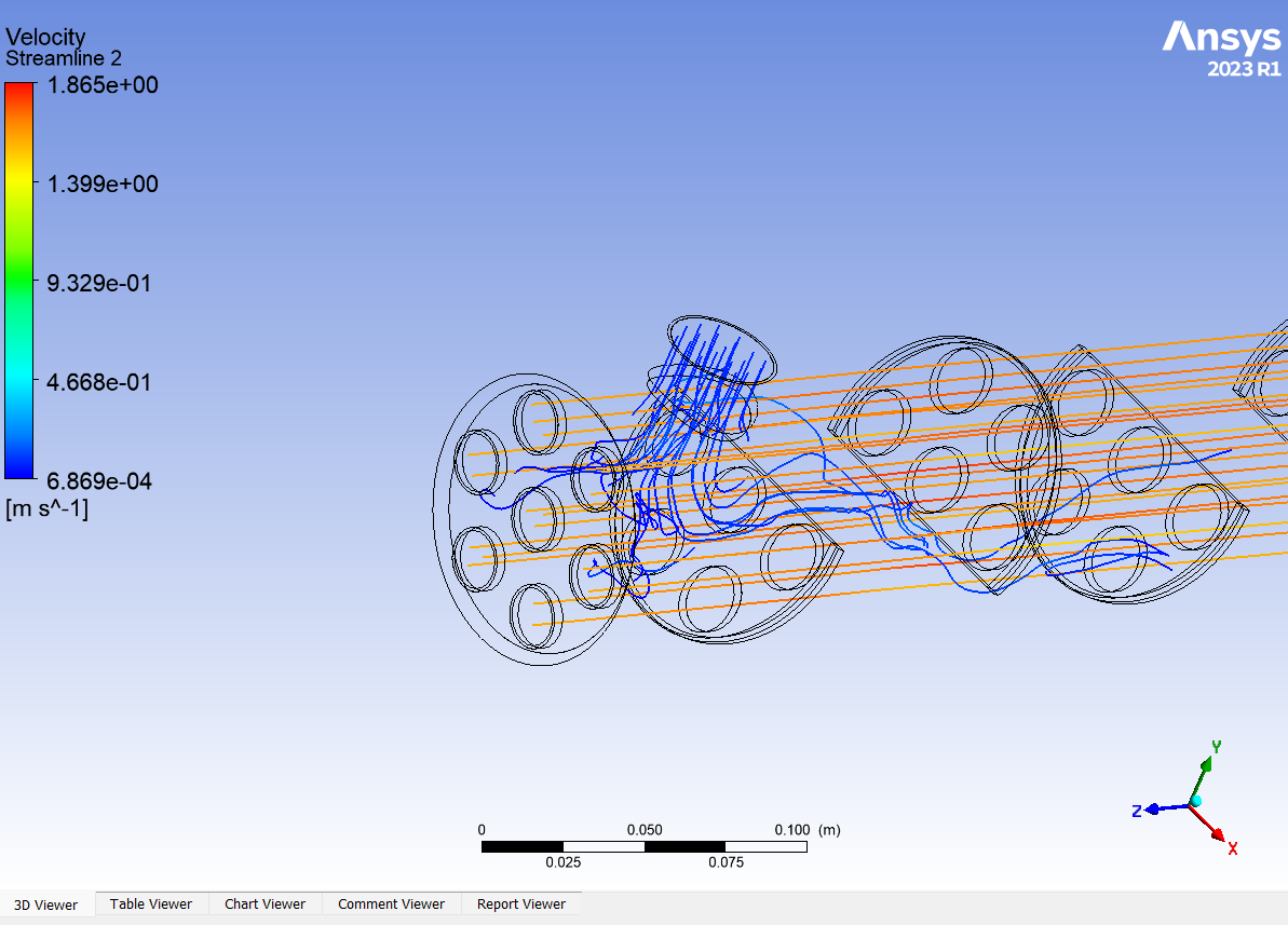
Results
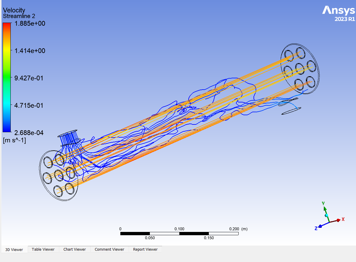
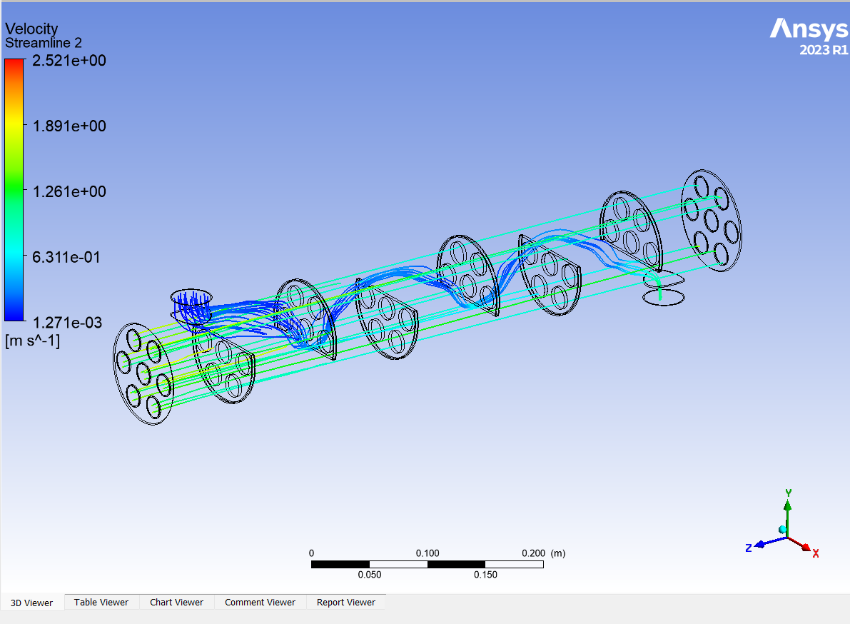
The outlet temperature for different designs are:
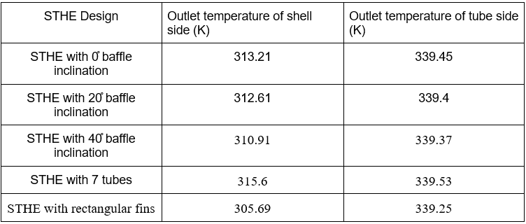
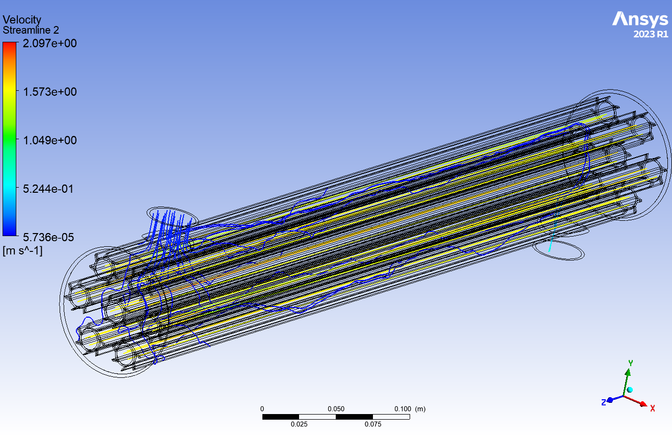
Velocity Streamlines
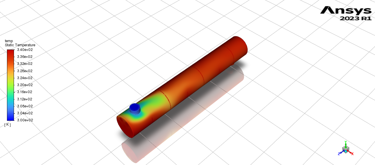
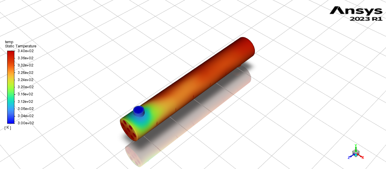
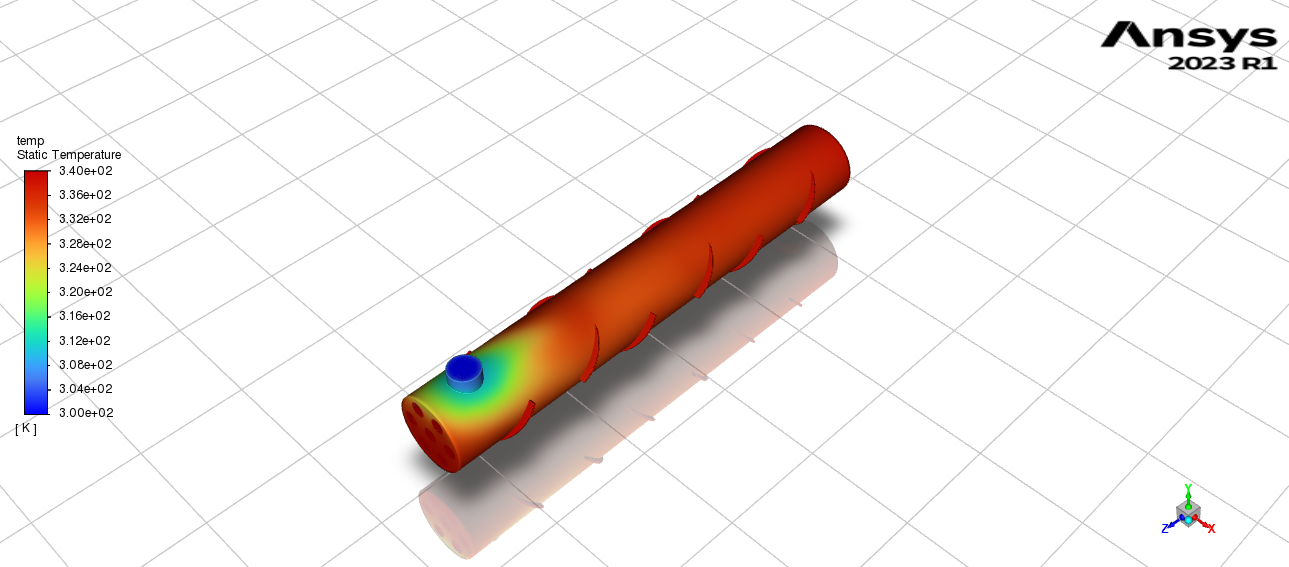
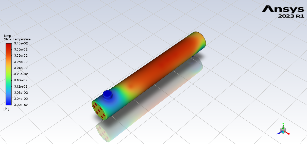
Temperature Contours
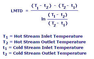
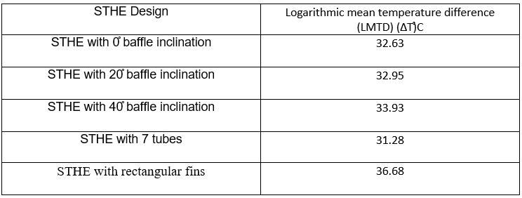
LMTD
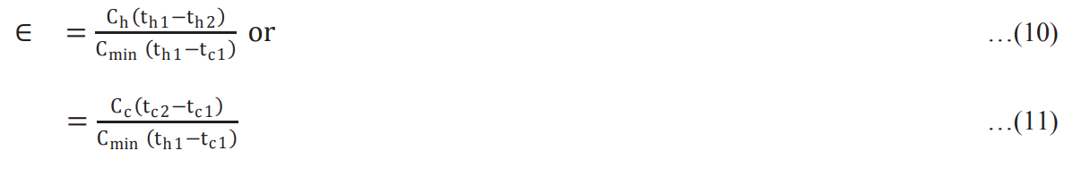
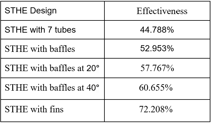
Effectiveness
Conclusion
The Logarithmic Mean Temperature Difference(LMTD) is higher for Shell and Tube Heat Exchanger with shell side enhancements like segmented baffles than for Shell and Tube Heat Exchanger with no shell and tube side enhancement. Fins as a tube side enhancement show the greatest LMTD. The Heat Exchanger effectiveness is higher for segmental baffles with inclination compared to segmental baffles with no inclination. This is due to higher turbulence and better heat transfer at greater baffle inclination angles(angle>0).Baffle with 40° inclination shows the best performance. The Outlet temperature for design with fins is greatly reduced when compared to other designs due to more heat transfer from hot to cold fluid. The most effective enhancement for the Shell and Tube Heat Exchanger are the fins as they provide the greatest heat transfer area amongst all the designs.
References
- Thermo-hydraulic performance analysis of converging-diverging heat exchanger with inclined fins using computational fluid dynamics
- Computational Fluid Dynamics (CFD) analysis of the heat transfer and fluid flow of copper (II) oxide-water nanofluid in a shell and tube heat exchanger
- Design and CFD Analysis of Shell and Tube Heat Exchanger
- Heat transfer enhancement, intensification and optimisation in heat exchanger network retrofit and operation