Mentors
- Harshavardhan S
Members
- Shannon Britney Carlo
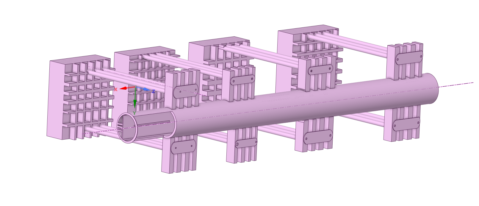
Aim
- To design a simple SFTB
- To find out it’s Eigen periods
Introduction
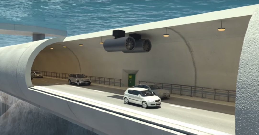
Water bodies could be considered as one of the main barriers in the transportation point of view. However, meddling with these water bodies to make the bridges is not always recommendable. Moreover, roads above the land have chances of snowfall, rainfall or any such bad weather conditions, especially where the need of a bridge is higher. This is where the Submerged Floating Tunnel comes into picture.
Why do we need SFTBs?
- Exerts little influence on the surrounding environment of the SFTB structure
- Rarely impedes navigation or local beauty as it is immersed in water
- Can operate in any weather
- More economic advantage than the traditional tunnel or bridge
- Travelling between countries through water will be faster
Design of the Submerged Floating Tunnel operating under various conditions
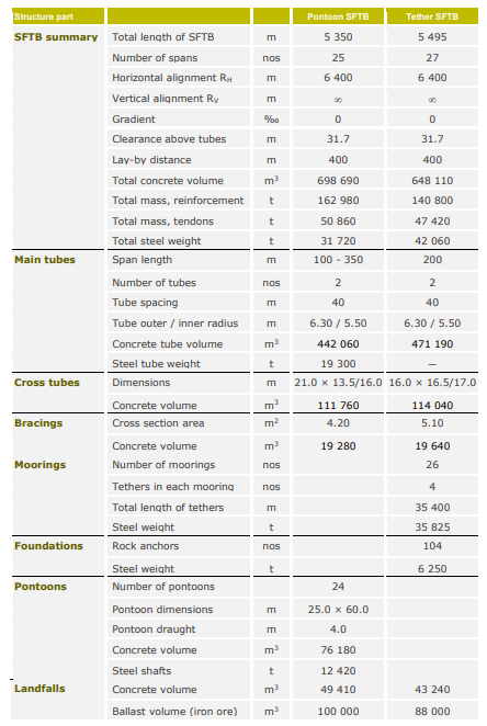
In Norway there has been identified several crossings with a variety of different conditions under which a Submerged Floating Tunnel, SFT or Archimedes Bridge, may be used. In the Høgsfjord project whose feasibility was well documented before the project was stopped for local political reasons the length was some 1400 m, the water depth about 150 m and the site was well protected from large sea waves. However, swell, vortex shedding and slowly varying internal waves due to layers of different salinity presented a hazard of significant dynamic oscillations. In the wake of the Høgsfjord project feasibility studies have been undertaken in Norway for sites at the very inlet of a fiord directly exposed to the big North Sea waves, in an inland lake with ice infested waters, in fiords threatened by large waves induced by huge, falling rock masses, and most recently the largest fiord in the country, the Sognefjorden which at the identified crossing site is 3700 m wide and 1250 m deep. In addition to the challenge of these various conditions some common accidental situations have to be solved for all applications including fire, sinking ships,falling anchors as well as sudden massive water ingress into the tube.
Typically an SFT consists of the following elements: The tunnel tube which provides space for the road and/or railway traffic.Tethers, vertical or inclined fixing the tube to the seabed at certain spacing.Pontoons mounted on top of the tunnel and “anchoring” it to the sea surface.Gravity anchors on the seabed providing support for the tethers.Shore connections at the ends of the tunnel The tubes may be constructed of steel,concrete or a combination of the two.The Tube is mostly designed with circular cross-sections, primarily from hydrodynamic reasons. Other shapes as elliptical,rectangular or multiple-sided may also be of relevance.
For design of an SFT the following basic considerations should be taken into account: 1)The cross-section must give sufficient space for traffic, evacuation, ventilation, ballast, inspection, maintenance and repair work 2)The alignment must be such that there is no interference with ship traffic passing above 3)The tunnel must have a simple and well defined static system which can be properly represented in the design calculations 4)The joints should have no less strength or integrity than the tube between the joints 5)The structure must have a ductile behaviour in the potential failure modes 6)The anchoring system should be redundant 7)The tunnel must not be unduly susceptible to local damage 8)The structural details must be simple and designed to avoid undue stress concentrations 9)The structure must be robust against changes in the static system, variations in the material properties and corrosion 10)The tunnel must behave in a satisfactory manner with regard to deformations, settlements and vibration 11)The tunnel must have a satisfactory safety against fatigue 12)The tunnel should be designed such that the water inflow rate is so limited that people have time to safe evacuation in case of massive water ingress 13)Tether lengths must be adjustable to compensate for e.g. possible settlements 14)Slack and snapping of the tethers must be avoided 15)It must be possible to repair or replace parts of the structure that are considered to have a shorter service life than the tunnel tube itself.Such parts can be tethers and other anchoring systems,bearings and moveable joints 16)For the first SFT’s and until sufficient experience has been gained with the concept,they should be designed and prepared such that steps could be taken to improve their behaviour,if proved necessary
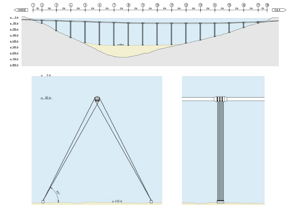
The ultimate solution is considered as SFT-crossing. This is a single tube stabilized by its own net weight and where both pontoons and tethers are eliminated. By having the apex at midspan the tube is stabilized by its net buoyancy. Massive water ingress can be made less dangerous since water then will flow towards prepared water basins in the rock sides at each end of the tube.
Dynamic effects and their challenges-
*Wave Loads- Non-linear effects in the waves create small unbalanced wave drift forces of which the so-called difference frequency loads will be long-periodic and may also cause resonances for the lower eigenmodes.Another source for such possible long-periodic resonances are the so-called internal waves.These are effects that generate from potential layering of water with different densities due to salinity variations. In fiords with significant supply of fresh water, a lighter layer of breakwater can exist on top of a more dense layer of sea water with higher salinity. The most important effect of this layering is the free internal waves which can give rise to wave forces on an object in the vicinity of a boundary between two layers. It has been estimated that such waves can occur at periods higher than 40 seconds. *Current Loads- On the tube the current gives rise to a constant in-line force which is proportional to the square of the current velocity. For a horizontal arch-shaped tube the symmetrical current profile is very well resisted by the axial forces in the arch, and the capacity of the arch is largely governed by its buckling capacity. An antimetrical current profile will not create significant axial forces in the arch, and the current forces have to be resisted by the bending moment capacity of the tube unless some supporting tendon systems or similar are introduced. The current speed may also have some slowly varying velocity components, which should be kept in mind when evaluating the potential for resonance phenomena induced by slowly varying forces. Current will give rise to vortex shedding when passing an obstacle. When passing a cylinder the vortex shedding occurs at a frequency that is proportional to the current velocity. When this frequency approaches the natural frequencies of the cylinder Vortex Induced Vibrations (VIV) occur. For a circular cylinder in-line vibrations typically start at a reduced velocity of Ur = 1-2 (Ur = Uc/(fn·D) where UC is the current speed, fn the natural frequency of the tube and D is its diameter) and cross-flow oscillations at a reduced velocity of typically 3-4. These oscillations are self-limiting in the sense that the in-line oscillations stabilize at an amplitude of some 0.15D while the cross-flow oscillations stabilize at amplitudes up to about 1.3D. It is interesting to note that simultaneous wave loading tend to reduce the amplitudes of vortex induced motions. For the tube such cross-flow oscillations should be avoided. With an outer diameter of a tube of some 16 m and a maximum current velocity of 1.5 m/s the fundamental period of the vertical vibration modes should then be lower than about 30 seconds. In-line vibrations are relatively small and present mostly a fatigue issue. For the tethers and tendon stiffening systems, however, it may be difficult to avoid cross-flow vibrations. Say the diameter of these members is 1m, then their fundamental period has to be lower than 3-4 seconds to avoid cross- flow vibrations when assuming that the governing current velocity is reduced to 1 m/s at the relevant water depth. Helical strakes may be a device used to suppress such vortex induced oscillations, if they do not have too severe negative side-effects such as increased current and wave loads. Galloping is an instability phenomenon that may occur in current at significantly higher current velocities than vortex induced vibration, typically at reduced velocities UR>= 10. Fortunately, galloping does not occur for cylinders with a circular cross-section. *Artificial Damping- There are many various sources of slowly varying environmental forces of low magnitude. As such, they would normally not do any harm to the SFT and its components if it had not been for the danger of resonance with major vibration modes of the tunnel tube.One safe way of dealing with this challenge is to design the tube and its supports such that the lower fundamental eigenperiods are safely below the periods of these forces.If it had been possible to design reliable artificial damping systems that could limit the resonance phenomena to tolerable levels, the number of such anchoring points and then also the cost could probably be significantly reduced. Such damping systems could be in the form of tuned mechanical dampers; i.e. internal mechanical systems that have eigenperiods tuned to the frequencies that should be damped out. The space below the roadway could be utilized for this matter. Also, heavy concrete blocks hanging in e.g. chains underneath the tunnel might have the same effect. This latter system could furthermore increase the hydrodynamic damping. Another possibility is, still under the roadway, to install water basins on each side of the cross-section and connect these basins with a tube. Water flow from one basin to the other induced by the motions of the tube could then create viscous damping.
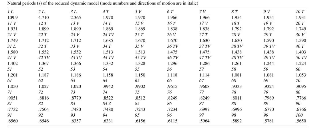
Hydrodynamic Response
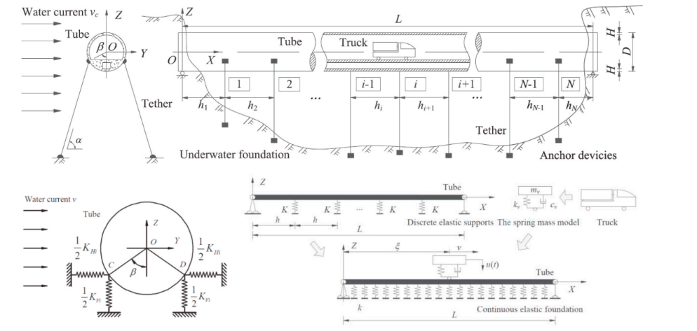
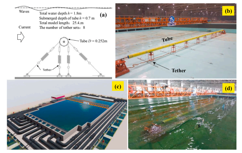
Submerged floating tunnel (SFT) is a new type of transportation infrastructure for crossing sea straits in relatively deeper water. Compared with the traditional fixed tunnel, the main challenge in SFT design is obtaining the hydrodynamic response parameters with a complex hydrodynamic environment. However, long span SFT (length > 5 km) and spatial difference of the hydrodynamic load along with the tunnel length bring unprecedented challenges in hydrodynamic response investigations. The existing analysis theory or method could not fully meet the requirement of the dynamic controlling design of long span SFT when considering complex ocean environment. We can systematically collate and review the research status and latest achievements concerning the hydrodynamic response investigation method of SFT from two aspects: mathematical model and physical modeling. Typical theoretical and/or numerical model for determination of hydrodynamic load, the tube response under wave current, the tether-tube-vehicle coupled analysis in wave and current and the global fluid-structure coupling analysis in the mathematical models are introduced, emphasis are given on the basis assumption, governing equations, environmental conditions and factor consideration. The major methods and output of 2D and 3D model tests in the physical modeling are also summarized. However, the existing mathematical models use a lot of simplified assumptions, which are efficient in relatively simple condition, but less flexible in treating the actual complicated hydrodynamic environment. The present physical model tests have difficult in properly simulating the end constraints, actual stiffness and structural elastic deformation of the SFT model.
Response of a SFT subject to flow induced vibration(FIV)
Cross-flow(CF) and in-line(IL) FIV under different hydraulic loading becomes crucial, inducing structural fatigue damage and affecting lifetime of SFT. If oscillatory flow due to vortex shedding periodically occurs and this synchronizes with the structural natural frequency, the SFTs amplitude and oscillation increases causing VIV(vortex induced vibration). VIV is a category of FIV and has ‘lock-in’ regime which shifts vortex shedding frequency to structural natural frequency. SFT is composed of complex coupled mooring tube-joint system. Structural material and Reynolds No of the flow affect FIV characteristics. For theoretical and semi empirical methods, the VIV response is based on Hamilton principle and later simplified as Euler-Bernoulli beams. Wake oscillator model is employed to determine the amplitude of vibration of SFT tethers. The use of CFD allowed VIV prediction but the previous design models neglected it due to use of potential flow model. SFT model as a system of rigid segments connected with flexible joints and Gina gaskets (used between the sectional elements of immersed tunnels to prevent water ingress due to external water pressure) allows more realistic simulation of dynamic behavior.
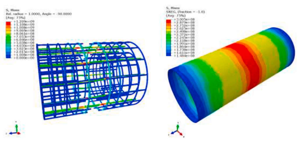
3D dynamic response of submerged floating tunnels under seismic and hydrodynamic excitation
A procedure for the nonlinear dynamic analysis of submerged structures under seismic or hydrodynamic excitation is being developed, especially to the aim of providing a reliable numerical tool for the design of innovative structures such as submerged floating tunnels. By the point of view of modelling, the key point of the procedure lies in the representation of the behaviour of the anchor elements connecting the tunnel to the seabed. Seismic analysis have been performed under the hypothesis of complete 3-D multiple-support excitation while response to hydrodynamic effects have been computed by considering nonlinear drag forces due to steady current and wind waves. The results here obtained point out some of the critical aspects of the tunnel behaviour under earthquake loading. When transverse oscillations are examined, tunnel behaviour appears to be rather predictable in terms of its linear behaviour. Flexural oscillations of long anchoring elements occur at much lower frequencies, while short ones, located at the tunnel sides, are subject to very high stressing, leading to inelastic behaviour. Finally, given the tunnel depth and eigenspectrum, its dynamic behaviour under hydrodynamic loading due to wind waves is characterized by very small amplitudes. Low frequency components of the wave field, however, are capable of exciting transverse flexural oscillations of the same order of magnitude as detected in extreme seismic conditions.
 under seismic excitation.png)
 under hydrodynamic excitation.png)
Accidental scenarios
Irrespective of how the SFT is designed possible accidental scenarios have to be identified and dealt with to minimize or possibly to eliminate their consequences. Pontoons may be subject to both local and more overall damage due to ship collision. Dividing the pontoons into compartments and introduction of weak links between pontoon and tube may be the answer to such threats. The tunnel tube may be subjected to scenarios such as sinking ships, impact from submarines, hooking of trawling gears and anchor lines, internal fire and explosion and water filling due to rupture of possible internal water mains. The ultimate consequence of these scenarios is massive water filling of the tube. The tunnel should be designed so that all potential failure modes be ductile. Other safety enhancing measures may be to use double hull,steel lining in case of concrete tubes and also to shape the tube so it has the apex at midspan such that possible incoming water flows towards the ends of the tube. Tethers and tendon systems may be subjected to impact from submarines, impact from trawling gears and anchor lines and also from sinking ships. These systems thus have to be redundant so that their individual elements may be repaired or replaced while the remaining system is fully operable.
Norwegian fjords
Submerged floating tunnels (SFTs) weigh roughly the same as the surrounding water. The loads on the tunnel depend on the variation of the forces on the tunnel. The forces come from variation in traffic, current, temperature, waves, weight of water, weight of concrete, growth on the tunnel, wear of asphalt, dust and debris, relaxation of prestress and shrinkage and creep in the concrete. The last six variations are slow and can be counteracted by altering weights in the tunnel. All structures above sea level are subject to gravity, which tends to limit their spans. In SFTs buoyancy counteracts gravity. This speaks for longer spans, but the slope of roads limit the depth to raise ratio of downward arched SFTs. This tends to limit the free spans. The Limfjord tunnel has a costly and complicated expansion joint. This joint could have been avoided if the tunnel had been allowed to float freely between the shores. All this would have made the tunnel much less costly. The shape of the SFT has been chosen for the following reasons: When the vertical curvature is concentrated in the middle of the SFT, it is easier to shorten the concrete tube during installation. The variations in the buoyancy in the middle of the tunnel introduce little bending in the tunnel.Similarly an unusual amount of water in the middle of the tunnel gives little bending and axial force.
Conclusion
The submerged floating tunnel will set up new trends in transportation engineering and which shows with the advances in technology that will reduce the time required for travelling. And make the transportation more effective by hiding the traffic under water by which the beauty of landscape is maintained and valuable land is available for other purposes. Benefits can be obtained with respect to less energy consumption, air pollution and reduced noise emission. For wide and deep crossings the submerged floating tunnel may be the only feasible fix link, replacing present days ferries and providing local communities with new opportunities for improved communication and regional development.
References
- Science Direct -Ocean Engineering- A global review for the hydrodynamic response investigation method of submerged floating tunnels
- Applied Sciences- Hydrodynamic Behavior of Submerged Floating Tunnels with Suspension Cables and Towers under Irregular Waves
- Engineering Failure Analysis- On the internal blast loading of submerged floating tunnels in concrete with circular and rectangular cross-sections
- Science Direct- Submerged floating tunnels for crossing of wide and deep fjords
- Marine Structures- Simplified analysis for estimation of the behavior of a submerged floating tunnel in waves and experimental verification