Ever wondered why exactly are high lift devices needed? Let me tell you…
Lift generated by wings of an aircraft is estimated by the following relationship,
\begin{equation} L = \frac{1}{2}\rho v^2 A C_L \end{equation}
Where:
$L$ = lift force generated
$\rho$ = air density
$v$ = true air speed
$A$ = lifting area of the wing
$C_L$ = coefficient of lift
Clearly, same amount of lift can be generated by various permutations and combinations of $\rho$, $v$, $A$ and $C_L$.
Now, let us think about situations when $v$ is quite less, take-off or landing for instance, that the lift generated cannot balance the total weight of the flight. At such situations, we need to alter the other three factors in order to make the aircraft fly. $\rho$ is something that is quite out of our control. Hence, we need to do something which increases the other two factors. Here is where high lift devices come into the play.
Knowing CL
One should know how $C_L$ behaves, before one can commend the work done by the high lift devices. Airfoils are of various types. One of the basic types of differentiating them is into symmetrical and cambered airfoils.
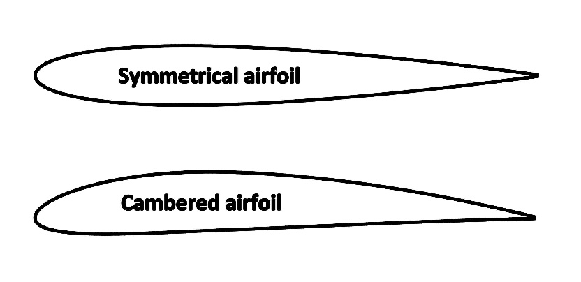
The above figure represents the difference between symmetrical and cambered airfoils schematically. Let us look what effect cambering has on the lift of an airfoil.
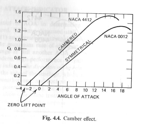
It can be seen that having a camber in the airfoil increases the highest attainable lift coefficient. However, there is a decrease in the critical angle of attack, which is the highest angle of attack that can be deployed without letting the airfoil to stall.
What is this stall then?
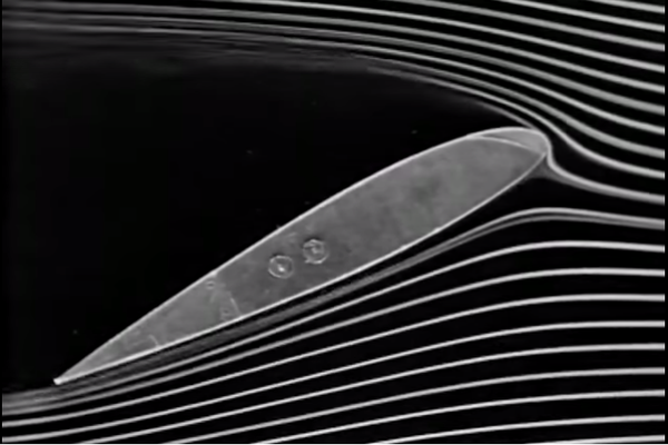
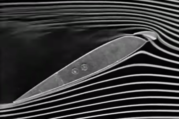
Air does have certain viscosity and it does develop a boundary layer. Thus, the molecules in the boundary layer experience viscous forces against each other. In addition to this, they might also have to face adverse pressure gradients along their way ahead along the boundary layer. Hence, the molecules which become devoid of energy while they try to overcome both viscous forces and adverse pressure gradients, cease to continue in the boundary layer and get separated from the skin of the airfoil. This is what is called as a stall.


When M. S. Dhoni, or Sachin Tendulkar if you think of him, faces a similar situation, he takes a cup of Boost in order to continue playing. On similar lines, if one can, somehow, provide energy to the flow, the stall will be delayed thus making it possible to increase the critical angle of attack.
So, in order to increase the lift supporting area of the wing and to increase the lift coefficient either by increasing camber or by delaying stall or both, some special devices are used known as High Lift Devices.
High Lift Devices
There are various ways in which the aforesaid objectives can be met. Following are some of those.
Flaps
These are the high lift devices (HLDs) that are generally deployed at the trailing edge of the wings. These devices, change the effective camber of the wing cross sections. Flaps are again of different types. The following figure illustrates some.
Slats and Slots
These are the HLDs usually placed at the leading edge of the wings. Slats are small, retractable airfoils attached to the wing leading edges, generally just before the ailerons so that the latter remain operable even when rest of the wing enters stall. When slats are made open, they create slots (gaps) between them and the main airfoil and high pressure air on the lower surface of the airfoil is directed to the upper surface, making the flow over the upper surface smoother and delaying the stall to higher angles of attack. The effect of flaps and slats is shown below.
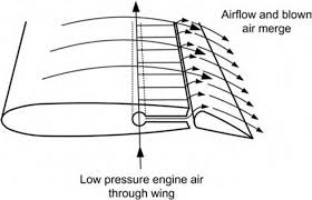
Boundary layer control and Blown Flaps
These come under the powered high lift systems. Generally, these systems involve blowing of air from some powered source, like compressor of an engine or exhaust of the engine, using ducts and other mechanisms to achieve the desired lift characteristics. Here is a small description of such devices.
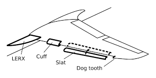
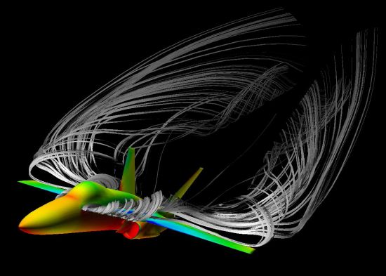
Leading Edge Root Extensions
A LERX typically consist of a small triangular fillet attached to the wing leading edge root and to the fuselage. In normal flight the LERX generates little lift. At higher angles of attack, however, it generates a vortex that is positioned to lie on the upper surface of the main wing. The swirling action of the vortex increases the speed of airflow over the wing, so reducing the pressure and providing greater lift. LERX systems are notable for the potentially large angles in which they are effective.