“JARVIS, Suit me Up!”, Clang! Spoof! Phew!, Tony Stark becomes IRON MAN!
Have You Ever Wondered, what if, just like that, with one cool move you too could control and move objects around you; OR Maybe develop a gesture-controlled game like in the movie Ra. One? Well, here I have tried to design and build a mini version of it; a Robot controlled by hand gestures.
But first up, what exactly is a Gesture Controlled Robot?
A Robot which detects any movement(gesture) and functions depending upon these signals is a Gesture Controlled Robot. They can use different technologies viz. accelerometer-based sensing (wired or wireless) or image processing.
Here we will implement an accelerometer-based, wireless gesture-controlled robot.
What you need to have.
The bot has two sections- transmitter and receiver. You will need Ht12e (encoder ic), Ht12d (decoder ic), L293D (motor driver shield), Arduino uno,7805(voltage regulator ic), capacitor, PBT connector, single pole antenna, resistor, LED, accelerometer and battery.
How does it work and recognize the gestures?
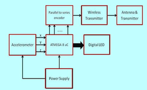
The brain of this robot is the Arduino Uno (Atmega32) which is fed with a set of code. The gestures/motion made by hand are detected by an acceleration measuring device, called accelerometer (ADXL335).
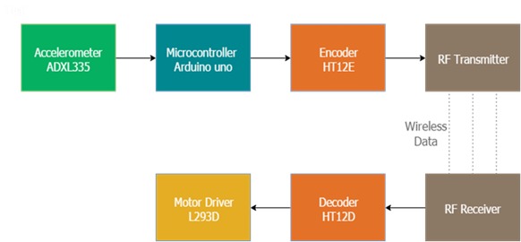
The accelerometer reads the X Y Z coordinates when we make gestures by hand and sends them to the Arduino. The Arduino checks the values of coordinates and sends a 4-bit code to the Encoder IC. The Encoder passes the data to an RF transmitter and the transmitted data is received by an RF receiver. The receiver sends the 4-bit code to the Decoder IC which then passes it to a Motor Driver IC. It later takes the decision to turn the two motors in the required direction.
What is an Accelerometer?
An accelerometer is a type of sensor which gives data in Analog form while moving in the directions of X, Y and Z(these directions depend on the type of sensor). It consists of direction arrows; if we tilt the sensor in one direction, then the data at that particular pin will change in analog format. The accelerometer consists of six pins. The function of each pin is discussed here.
-
Pin-1: VDD pin is used to give +5V supply.
-
Pin-2: GND pin is connected to the ground to ensure biasing.
-
Pin-3: X pin will receive the data from the X direction.
-
Pin-4: Y pin will receive the data from the Y direction.

-
Pin-5: Z pin will receive the data from the Z direction.
-
Pin-6: ST pin is used to adjust the sensitivity of the accelerometer i.e. 1.5g or 2g or 3g or 4g.
Making the power supply.
You will need:
-
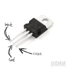
An IC 7805 which regulates the 12V supply to 5V (if you can’t get a 12V supply you can use a 9V supply)
-
0.1uf and 470uf capacitors
-
1k resistor for status LED
Let’s start with the power supply circuit. You will need two such circuits: one for the transmitter and one for the receiver. The receiver circuit needs to be powered using a 12V supply (since we are using a 12V motor), and the transmitter circuit can be powered using a 9V battery.
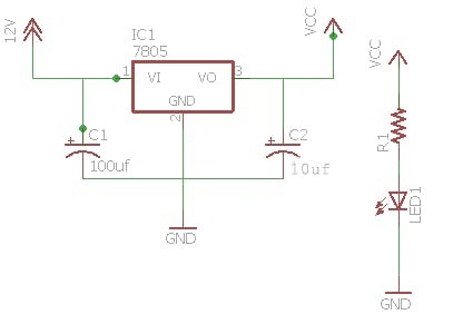
You can see the circuit diagram for the receiver power supply on the right. Using this diagram, rig up the supply circuit. You can also add an LED via a 1K resistor to indicate the state of power supply.
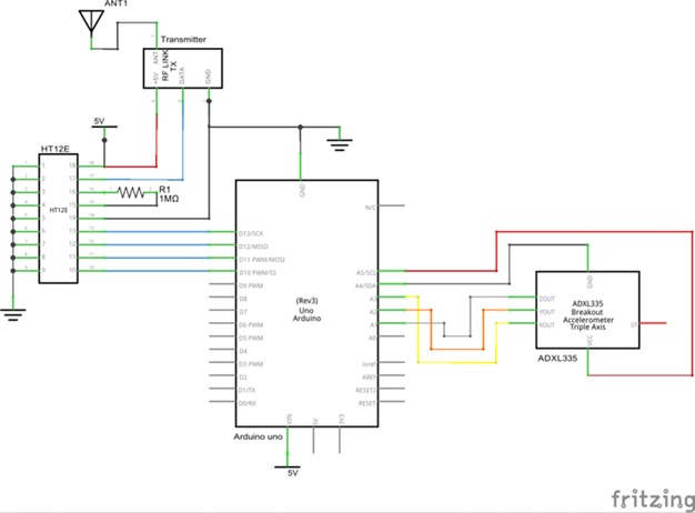
Let’s Move Ahead to make the Transmitter (Remote)
The transmitter section consists of an accelerometer which detects the hand gestures and sends the data to the Arduino. This then sends the data to an Encoder IC which is subsequently transmitted to a receiver.
The RF TX module works with 433MHz frequency and is easily available in the market at low cost.
Wire it up as per the below circuit diagram:
Code the Arduino to make it function like how you want it to.
Motor Driver
The motor driver is a device which gives the movement to do a task like a motor. So, we require motor driver to run them through the controller. The interface between motor & microcontroller can be done using an L293D motor driver IC in this circuit.
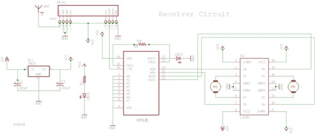
Receiver circuit
The receiver circuit consists of 2 IC’s (HT12D decoder, L293D motor driver) and an RF receiver module.
Wire the circuit as per the above receiver schematic. There are 2 LED’s in the receiver board; one lights up when the power supply is given to the receiver and the other when power supply is given to the transmitter. The LED near the IC HT12D should light up when power is given at the transmitter, thus ensuring a valid transmission (VT). If it doesn’t, then there is something wrong with your connections or your RF-TX-RX module.
The Final Working
Accelerometer based gesture-controlled robot moves according to the movement of the hand, since the accelerometer is on your hand. When you tilt your hand forward (with the accelerometer on your hand), the robot moves straight ahead. When you tilt backwards, it changes direction and starts moving in reverse. When you tilt to the right, it starts moving rightwards and similarly to the left. (This is in accordance with what code I have written for the motion of my bot. You can modify accordingly!)
Enjoy driving your robot!!!
Note
-You can refer to the previous blog - How to get started with bots by -Tarun Mittal (dated June 1st ,2017) to get more insight into working of bots.
Some basic arduino tutorials :