The CAN Bus protocol stands for Controller Area Network Protocol, which is a two wired, bidirectional serial bus communication method. It was designed to perform in harsh environments such as in the automotive industry, but now it has emerged as a go-to network technology in industrial automation as well as in other applications. CAN define the data link and physical layer of the Open Systems Interconnections (OSI) model, thus providing a low-level networking solution for high-speed in-vehicle communication. CAN Bus is primarily used in embedded systems and provides fast communication among microcontrollers up to real-time requirements, thus eliminating the need for the much more expensive and complex technologies.
History
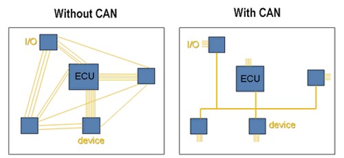
The controller Area Network (CAN) was originally developed by Bosch in 1986 for in-vehicle networks. Before that, automotive manufactures connected electronic devices in a vehicle using point-to-point wiring systems. Point-to-point wiring systems were those in which all the electronic components had their data line wired individually. As manufacturers began using more and more electronics in vehicles the wiring harnesses became more heavy and expensive. So they replaced the primitive point-to-point wiring system with in-vehicle networks.
As the CAN communication protocol had high immunity to electrical interference and the ability to self - diagnose and repair data errors, the automotive industry readily adopted the CAN Bus Protocol, and later in the year 1993 it became the international standard known as ISO 11898. Since 1995 many Higher Layer Protocols (HLPs) were developed for and standardized on CAN.
Today, CAN is found in almost every market while developments are continuing in the area of HLPs to support the needs of existing and new developers.
What makes CAN Bus special?
-
Simple Design - CAN provide a cost effective robust communication network. Due to the simple design, the ECU has only a single CAN interface rather than analog and digital inputs to every device in the system thus it reduces error, cost, and weight of the wiring.
-
Broadcast Communication - The CAN protocol uses a peer-to-peer network which means that every electronic module or ECU connected to the Bus can receive and transmit data to all other modules or ECUs and sees all the transmitted messages, thus the message can take multiple routes to get to the destination. This feature adds to the robustness of the CAN protocol as even if one module on the CAN bus fails, it does not necessarily cause the failure of other modules.
-
Priority Id System- Every message transmitted through the CAN Bus has a priority Id, So in case if two or more nodes in the Bus tries to transmit messages at the same time the message with higher priority is considered first and the other message is processed after this.
-
Cyclic Redundancy Check- The CAN Bus protocol uses a cyclic redundancy code(CRC) in each of its message frames. Thus this helps in identifying the errors in the transmitted frame’s content and after error identification that particular message frame is disregarded by all nodes.
-
Fully Centralized- The CAN Bus provides a single point of communication with all the ECUs enabling central diagnostics, data logging, and configuration.
Structure of CAN Frames
Communication over the CAN Bus is done via CAN frames. The original ISO laid out what is called a Standard CAN. Standard CAN uses an 11-bits identifier for different messages, later CAN was modified and the identifier was extended to 29-bits which is known as Extended CAN.
Standard CAN
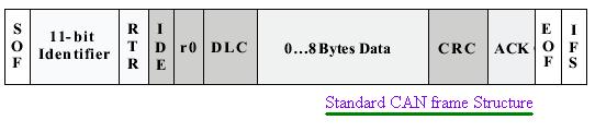
The meaning of the bit fields of the above figure is -
- SOF - The single Start of Frame(SOF) bit marks the start of the message and is used to synchronize the node on a bus after being idle.
- Identifier - The 11- bit Identifier establishes the priority of the message, the lower the binary value, the higher is its priority.
- RTR - The single remote transmission request (RTR) bit is dominant when the information is required by another node. All the nodes present on the CAN Bus receive this request but the identifier determines the specific node. The responding data is also received by all the nodes and can be used by any node interested.
- IDE - A dominant single Identifier extension(IDE) bit means that a standard CAN identifier with no extension is being transmitted.
- r0 - Reserved bit
- DLC - the 4-bit data length code(DLC) contains the number of bytes of data being transmitted.
- Data - Up to 8 bytes of application data can be transmitted.
- CRC - The 16-bit cyclic redundancy check (CRC) contains the checksum (number of bits transmitted) of the preceding application data for error detection.
- ACK - After every node receives an accurate message it overwrites this recessive bit by a dominant bit indicating an error-free message has been sent. ACK is 2 bits long one bit is the acknowledge bit and one is a delimiter.
- EOF - This end-of-frame (EOF), 7-bit field marks the end of a CAN frame and disables bit-stuffing, indicating a stuffing error when dominant. When 5 bits of the same logic level occur in succession during normal operation, a bit of the opposite logic level is stuffed into the data.
- IFS - This 7-bit interframe space (IFS) contains the time required by the controller to move a correctly received frame to its correct position.
Extended CAN
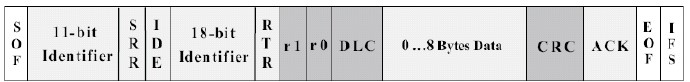
As shown above, the Extended CAN is the same as Standard CAN with the addition of -
- SRR - The substitute remote request (SRR) bit replaces the RTR bit in the standard message location.
- IDE - A recessive bit in the identifier extension (IDE) indicates that more identifier bits follow. The 18-bit extension follows IDE.
- r1 - Following the RTR and r0 bits an additional reserve bit has been included ahead of the Data Length Code bit.
How CAN Communication Works
CAN data transmission uses a lossless bitwise arbitration(the process in which two or more CAN controllers agree on who is to use the bus) method of contention resolution. This arbitration method requires all nodes on the CAN network to be synchronized to sample every bit on the CAN network at the same time. The CAN Bus consists of two wires CANH and CANL, when the controller sends a stream of bits, these are complemented and placed on the CANH line. The CANL line is always the complement of CANH.
The CAN specifications use the terms “dominant” bits and “recessive” bits, where dominant is a logical 0 and recessive is a logical 1. The idle state is represented in the CAN Bus is by the recessive level. If one node transmits a dominant bit and another node transmits a recessive bit then there happens a collision and the dominant bit wins. This means there is no delay to the higher-priority message, and the node transmitting the lower priority message automatically attempts to re-transmit six-bit clocks after the end of the dominant message. This makes CAN very suitable as a real-time communications system.
The exact voltages for a logical 0 or 1 depend on the physical layer used, but the basic principle of CAN requires that each node listens to the data on the CAN network including the transmitting node itself. If a logical 1 is transmitted by all transmitting nodes at the same time, then a logical 1 is seen by all of the nodes, including both the transmitting node and receiving node. If a logical 0 is transmitted by all transmitting nodes at the same time, then a logical 0 is seen by all nodes. If a logical 0 is being transmitted by one or more nodes, and a logical 1 is being transmitted by one or more nodes, then a logical 0 is seen by all nodes including the node transmitting the logical 1. When a node transmits a logical 1 but sees a logical 0, it realizes that there is a collision and a high priority is being sent thus it quits transmitting. By using this process, any node that transmits a logical 1 when another node transmits a logical 0 re-transmits the message six-bit clocks after all the high priority message ends and the CAN frame bit-stream continues without error until only one node is left transmitting. Since the 11 (or 29 ) bit identifier is transmitted by all nodes at the start of the CAN frame, the node with the lowest identifier transmits more zeros at the start of the frame, and that is the node that wins the arbitration or has the highest priority.
CAN Message Types
Four different types of frames can be transmitted through a CAN Bus -
- The Data Frame- The data frame comprises the Arbitration Field, the Data Field, the CRC Field, and the Acknowledgment Field. The Arbitration Field contains an 11-bit identifier and the RTR bit, which is dominant for data frames. Next is the Data Field which contains zero to eight bytes of data, and the CRC field which contains the 16-bit checksum used for error detection. Last is the Acknowledgment Field.
- The Remote Frame- The intended purpose of the remote frame is to help in the transmission of data from another node. The remote frame is similar to the data frame, with two important differences. First, this type of message is specifically marked as a remote frame, and secondly, there is no data.
- The Error Frame- The error frame is a special message that violates the formatting rules of a CAN message. It is transmitted when a node detects an error in a message and causes all other nodes in the network to send an error frame as well. The original transmitter then automatically retransmits the message.
- The Overload Frame- The overload frame is similar to the error frame in terms of the format, and it is transmitted by a node that becomes too busy. It is primarily used to provide for an extra delay between messages.
Conclusion
This blog introduced CAN Bus Protocol. To summarize CAN Bus is a robust serial communication network protocol that is suitable to work in harsh working environments. CAN uses a differential signal, which makes it more resistant to noise, along with a priority arbitration scheme for non-destructive message transmission.
References
- https://www.microchip.com/stellent/groups/SiteComm_sg/documents/DeviceDoc/en558265.pdf
- https://en.wikipedia.org/wiki/CAN_bus
- https://www.csselectronics.com/screen/page/simple-intro-to-can-bus/language/en
- https://www.allaboutcircuits.com/technical-articles/introduction-to-can-controller-area-network/
- https://www.ni.com/en-in/innovations/white-papers/06/controller-area-network–can–overview.html
- https://www.ti.com/lit/an/sloa101b/sloa101b.pdf
- https://sewelldirect.com/blogs/learning-center/understanding-can-bus-and-can-loggers