RADAR IMAGING
The World Wars were undoubtedly the worst things to happen to mankind but, they also birthed some ground breaking technology that is till date being used, one such example is the RADAR, acronym for Radio Detection and Ranging.
RADARs are a combination of EM transmitters and receivers that can be used to detect the presence of objects in a particular range specified for that RADAR. The principle involved is the reflection of the EM waves off the target and detection by the receiver of the RADAR.
The diagram represents a high level representation of monostatic RADAR, i.e. the RADAR unit consists of both the transmitter and receiver , both turning on/off alternatively by using a duplexer.
In this article Pulse RADARS are discussed. Range can be more accurately measured by Pulse RADARs.
EM waves are transmitted in a pulse and time is given for reception before the next pulse transmitted.
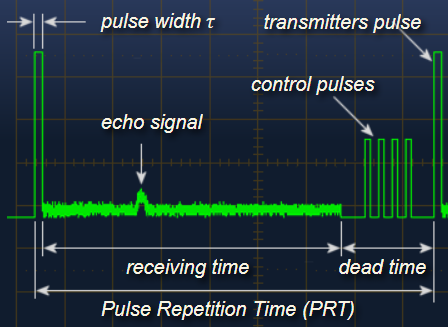
The entire time taken for transmission and reception is called Pulse Repetition Interval (PRT) as the next pulse is transmission happens after the previous one after one PRT.
The RADAR transmits EM waves in certain directions and targets are detected when the EM waves get reflected off the target and received by the RADAR. The time delay between transmission and reception of the EM wave is recorded and thus the Radial Range of the target is calculated as
R= c * t/2
c is the velocity of EM wave
t is the time delay between transmission & reception
The Radial Velocity of the target can also be measured by the frequency deviation between the transmitted and received wave, this phenomenon is called the Doppler Effect.
The EM waves transmitted by the RADAR can be reflected by more than one point on the target (eg: aeroplane), these points can be called Scattering points and the ability of the RADAR to recognize the target largely depends on its ability to differentiate between these points, this property is called Range Resolution.
Range Resolution is the minimum separation in range of two distinguishable points.
The resolution of Pulse RADARs inversely depends on the pulse width, but if the pulse width is too less, the intensity of the transmitted wave and thus the received wave will decrease. Thus, to solve the problem of this trade off, a technique called Pulse Compression is used.
Pulse compression is a signal processing technique of modulating the transmitted pulse and then correlating the received signal with the transmitted pulse. There are several types of Pulse Compression methods some of which are Linear Frequency Modulation ( LFM ), Stepped frequency , Costa's frequency coding.
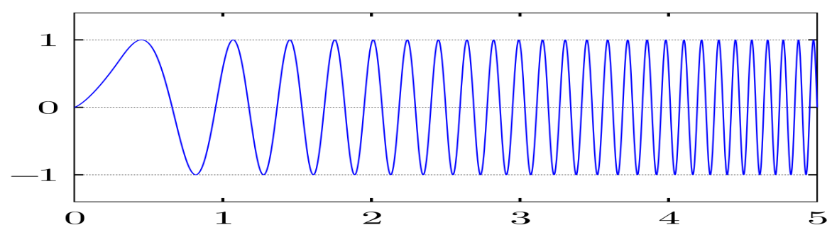
Linear Frequency Modulated wave , the frequency is proportional to the time in the pulse .
There are two prominent types of RADAR imaging: SAR and ISAR
SAR (Synthetic Aperture RADAR) is when the RADAR is moving and ISAR (Inverse Synthetic Aperture RADAR) is when the RADAR is stationary.
There are two important elements of a RADAR image, Range & Cross Range.
Range is distance along the axis in the direction of the propagation of the beam. It is taken as the component of Slant Range (radial distance)along the line joining the RADAR and the centroid of the target.
Cross range is the distance along the axis perpendicular to that of Range.
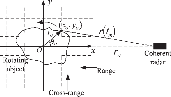
In RADAR imaging, the Range profile is obtained by the time delay between transmission and reception, while, the cross range profile of the target is obtained by the doppler frequencies obtained in the received signals.
While Range resolution can be obtained by Pulse Compression, Cross Range Resolution is obtained by having narrow beam, which requires larger antennas, but as this imposes physical challenges, Synthetic Aperture RADAR were made, i.e. a small antenna emulates a bigger aperture antenna by using the RADAR's movement relative to the target and some processing techniques. Rotation of the target relative to RADAR is essential
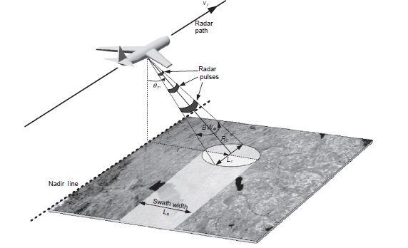
SAR
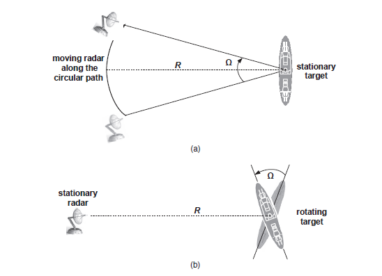
ISAR
The Doppler shift in frequency is caused by radial component of the velocity of a point alone and we can observe that when there is rotation of a target, different resolvable points will have relatively different radial velocity and thus will induce different Doppler shifts and thus the relative position of each scattering point can be obtained in the Cross Range profile.
RADAR imaging is a very useful technique and has both civilian and military applications. For example, SAR imaging can be used to survey landscapes and terrains, ISAR imaging has military application of recognizing flying objects in an airspace.
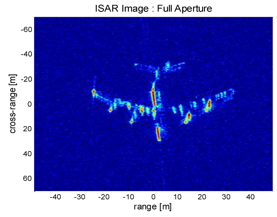
ISAR image of a passenger aeroplane
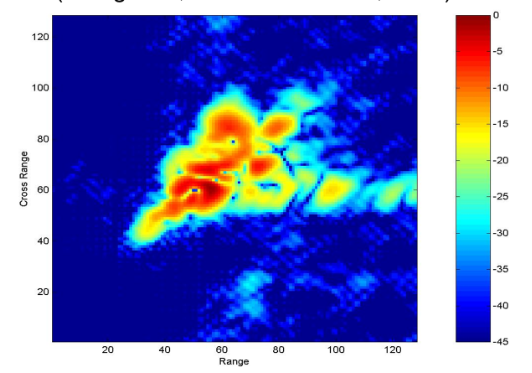
ISAR image of a Fighter Jet
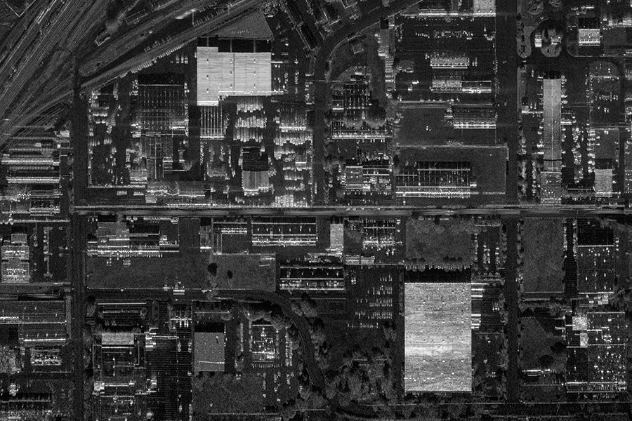
SAR image
References:
http://www.radartutorial.eu/index.en.html
Inverse Synthetic Aperture Radar Imaging With MATLAB Algorithms - Caner Ozdemir